General information regarding the modeling of acoustic structures using SILDIS® software
The SILDIS®[0] software (in Excel format) enables the modeling and optimization of multilayer acoustic structures for sound absorption and noise reduction. The COALA[1] calculation routine lies at the heart of various software modules:
- Module 1: prediction of the acoustic and aeraulic (aerodynamic) performance of dissipative silencers
- Module 2: prediction of the acoustic performance of plane partitions (including orthotropic panels, e.g. those with corrugations)
The relating input data are also used in another software module:
- Module 3: Prediction of the acoustic performance of duct walls
These modules facilitate the sizing of soundproofing products and construction systems (the SILDIS® software publishing and the engineering work carried out by ITS using the software have consistently been assessed as compliant with ISO 9001 requirements since 2015):
- within the scope of engineering projects
- within the scope of Research and Development (R&D)
They can be used:
- by ITS personnel responsible - besides computations with the software in various contexts - for programming, software marketing, training, and support ("internal use")
- by external users, then in general with reduced functionality (e.g. at their request) to minimize questions from potentially inexperienced users regarding input data, model selection, and settings, and to optimize usability ("external use")
A distinction is therefore made hereafter between the two modes of use: "internal use" and "external use"; this distinction is however not rigid or definitive, as a partial reversal of the reduction in functionality may be envisaged in some cases.
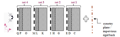
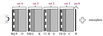
Returning to the COALA routine, it enables performance simulations for multilayer acoustic structures combining 1 to 4 sets (numbered 1 to 4 from back to front), potentially including:
- porous media: layers C, G, K, O e.g. mineral wools or others (e.g. glass or metal-based), foams)
- cloths (facings): D, H, L, P (e.g. glass cloths, needle-punched mats, fabrics)
- perforated protections: layers E, I, M, Q (e.g. perforated plates; the base material type does not require a distinction)
- thin plates: layers F, J, N, R (only when the performance to be evaluated relates to transmission through the resulting assembly e.g. characterized by its sound reduction index) e.g. plates made of metal, glass, plaster, or wood); an additional set (numbered 0) may optionally be included behind set 1
The foregoing applies to any single acoustic structure i.e. excluding cases where sound-absorbing linings differ on either side of a dissipative silencer's air passage (in which case, a single set is considered for each side).
At the rear of each multilayer acoustic structure, the following is considered:
- either an impervious rigid back e.g. downstream extremity of a standing waves tube (Kundt's tube) the floor of a reverberation chamber, the casing of a silencer, or a symmetry plane (i.e. the mid-plane of a rectangular splitter baffle silencer with symetric sound absorbing lining); in this case, thin plates are not taken into account[3] (cf. Figure 1)
|
Figure 1 multilayer acoustic structure without thin plate(s), with an impervious rigid back or or rear symmetry plane modeled with SILDIS® software |
- or a rear atmosphere i.e., a fluid (e.g. air)[2] not only when the performance to be evaluated relates to transmission through such a partition (e.g. characterized by its sound reduction index), but also when it relates to sound absorption (e.g. characterized by its sound absorption coefficient) in cases where the acoustic structure itself forms part of an enclosure separating the interior from the exterior (then: without an impervious rigid back) (cf. Figure 2)
|
Figure 2 multilayer acoustic structure with thin plate(s) and a rear air atmosphere modeled with SILDIS® software |
The electro-acoustic analogy used for an acoustic structure modeled with SILDIS® software is illustrated in Figure 3 (pi = incident acoustic pressure in Pa; p = acoustic pressure accounting for reflections in Pa; v = particle velocity in m/s; Zs = impedance of the acoustic structure, including the rear layer (impervious rigid backing or atmosphere) in Ns/m³; Zc = characteristic impedance of the fluid in Ns/m³; Θ = angle of incidence of sound waves relative to the normal to the acoustic structure's surface plane, in degrees). Almost all acoustic calculations are performed in narrow bands and displayed in 1/3 and/or 1/1 octave bands; overall values relative to a selected reference spectrum are calculated whenever appropriate.
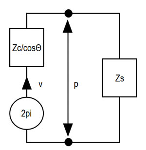
Figure 3 simplified electro-acoustic analogy for an acoustic structure as modeled using SILDIS® software |
For each layer, it is possible to:
- take it into account or not using a binary indicator (0/1); this allows for the consideration - for the sole the acoustic structure excluding the front atmosphere and the rear impervious rigid back/axis of symmetry/rear atmosphere - of 1 to 4*4 +1 = 17 material layers, thereby significantly broadening the range of possibilities for design and sizing of partitions and of sound absorbing linings e.g. for parametric optimization studies
- assign a specific thickness and a context-specific temperature (to account for any potential thermal gradient depending on thermal resistance relating to thermal conductivity and thickness and depending on thermal flux) - for thin plates, this is done by selecting the number of identical, unbonded stacked plates constituting each layer in case of non-singleness -
For all simulation contexts relating to a unique acoustic structure, using - in one or another of the calculation routines - the surface impedance evaluated at the acoustic structure's most upstream layer: regardless of the data entered for each layer within each set (sets 1 through 4, or even set 0), the data actually used for calculations are those relating to sets with an index less than or equal to the maximum set index imax selected by the user (ranging from 1 to 4, 0 being possible only in case of rear atmosphere); any other input data are ignored.
Summary of simulation contexts relating to a unique acoustic structure, using - in one or another of the calculation routines - the surface impedance evaluated at the acoustic structure's most upstream layer, for which the maximum set index imax is taken into account SILDIS® software for "external use")
| Simulation context | Affected results Excel sheet |
| (Module 1) Prediction of the acoustic performance of dissipative silencers: calculation of propagation loss (Da.L), influencing the by-pass correction (Dc) and the insertion loss without consideration of self-noise (Di') |
"in-out CODIS1", "in-out CODIS2", for the "locally reacting absorber" propagation condition (symbol σx/σy=∞); depending on the software version considered |
| (Module 2) Prediction of the acoustic performance of plane partitions: calculation of the sound absorption coefficient for normal incidence (α₀) and for statistical incidence (αstat), affecting the Sabine absorption coefficient (αsab), the weighted sound absorption coefficient (αw), and the absorption class (as well as any other overall performance indicator, more or less atypical, if displayed) |
"in-out COPPA", "in-out COPPA0" |
Summary of simulation contexts relating to a unique acoustic structure, not using - in one or another of the calculation routines - the surface impedance evaluated at the acoustic structure's most upstream layer, for which the maximum set index imax is not taken into account SILDIS® software for "external use")
| Simulation context | Affected results Excel sheet |
| (Module 2) Prediction of the acoustic performance of plane partitions: calculation of the sound absorption coefficient for normal incidence (α₀) and for statistical incidence (αstat), affecting the Sabine absorption coefficient (αsab), the weighted sound absorption coefficient (αw), and the absorption class (as well as any other overall performance indicator, more or less atypical, if displayed) |
"in-out COPPA1", "in-out COPPA2" |
Summary of simulation contexts relating to a non-unique acoustic structure, for which the maximum set index imax is not taken into account SILDIS® software for "external use")
| Simulation context | Affected results Excel sheet |
| (Module 1) Prediction of the acoustic performance of dissipative silencers: calculation of propagation loss (Da.L), influencing the by-pass correction (Dc) and the insertion loss without consideration of self-noise (Di') |
"in-out CODIS4", "in-out CODIS6" (cf. figure 4), for the "locally reacting absorber" propagation condition (symbol σx/σy=∞); depending on the software version considered |
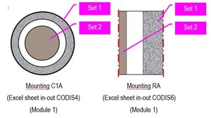
Figure 4 Layout of asymmetric silencers sound-absorbing packings modeled using SILDIS® software, for which maximum set index imax is not taken into account (cases with non-unique acoustic structure) |
For a given index set i ≤ imax, the inclusion of a material layer in the multilayer acoustic structure is automatic only in the case of a porous medium.
For cloths and perforated protections (modeled as series impedances):
- inclusion depends on a user-selected choice - for each layer - via a binary indicator (0/1) input
For thin plates (modeled as series impedances):
- inclusion depends on a user-selected choice - for each layer - via a binary indicator (0/1) input, in the sole simulation contexts where the consideration of thin plates is possible, given the programming of the performance indicator calculations (which the user cannot modify)
Summary of simulation contexts where the consideration of thin plates is possible, given the programming of the performance indicator calculations SILDIS® software for "external use")
| Simulation context | Affected results Excel sheet |
| (Module 2) Prediction of the acoustic performance of plane partitions: calculation of the sound absorption coefficient for normal incidence (α₀) and for statistical incidence (αstat), affecting the Sabine absorption coefficient (αsab), the weighted sound absorption coefficient (αw), and the absorption class (as well as any other overall performance indicator, more or less atypical, if displayed); calculation of sound reduction index |
"in-out COPPA" (1 to 5 plates i.e. multiple partition wall), "in-out COPPA1" (1 single plate i.e. single leaf-wall), "in-out COPPA2" (2 plates i.e. double leaf wall) |
| (Module 3) Prediction of acoustic performance of duct walls; calculation of sound reduction index |
"in-out CORED IN->OUT"," in-out CORED OUT->IN", "in-out COCID IN->OUT", "in-out COCID OUT->IN", the output data from these Excel sheets serving as input data for calculations in other modules; depending on the software version in question |
In some versions of the software, the materials making up the various layers can be selected from libraries, with the user always having the option to use custom parameters (BYO: Bring Your Own material references for porous media, facings, perforated protections, thin plates). In all cases and for all materials:
- physical properties (whether sourced from libraries included in the specific software version or entered by the user) are based on standard temperature and pressure conditions i.e. typical ambient laboratory conditions
- the software calculates the influence of temperature and pressure (as entered by the user) specific to the case under study
In all cases, input data can be selected by the user:
- either by entering numerical values (as the software operates in Excel format, this is done in designated cells highlighted in yellow)
- or by selecting a model from a drop-down menu for various stages of the calculations
Regarding the names of the Excel worksheets in the workbook that make up the module(s) of the SILDIS® program (depending on the considered version), those with names beginning with:
- "in": allow for user data input
- "out": allow for the viewing of output data (e.g. calculation results)
- "in-out": allow for both data input and the viewing of output data (e.g. calculation results)
|
Figure 5 Overview of the SILDIS® software's computation routines relating to the modeling of multilayer acoustic structures |
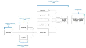
Thus, for "external use" (assuming clean, dry air), without prejudice to the specific material layers to be considered for the intended application, the input data to be entered into the "in-COALA" Excel sheet are:
- the front atmosphere temperature
- the front atmosphere pressure
- a binary indicator (0/1) determining whether or not a rear atmosphere is to be taken into account, and if applicable (i.e. if a rear atmosphere is considered and its temperature and pressure differ from those of the front atmosphere, the latter being displayed by default):
- the rear atmosphere temperature
- the rear atmosphere pressure
- the maximum set index imax
Accounting for porous media using SILDIS® software for the modeling and optimization of multilayer acoustic structures
The intrinsic properties of porous media that can be accounted for using the SILDIS® software are: airflow resistivity (σ), porosity (Φ), tortuosity (α), thermal characteristic length (Λ'), viscous characteristic length (Λ), and bulk density (RG).
For "internal use," a wide range of models for acoustic behavior indicators of porous media (wave number (k)/propagation constant (Γ), characteristic impedance (Zc), elastic modulus (K), effective density (ρ)) are implemented:
- allowing for the inclusion of 1 to 5 of these properties (at a minimum: airflow resistivity σ)
- with some models dedicated to specific types of infill material (e.g. basalt wool, rock wool, glass wool, polyester wool), while others are versatile enough to accommodate other materials, such as ceramic fibers or foams
- for the porous medium of set 1 (not for the other sets): taking into account an eventual potential anisotropy i.e. a difference between properties normal to and perpendicular to a fiber orientation plane
In the software versions generally marketed by ITS (i.e. for "external use"), regarding general models of the acoustic behavior of porous media, the following are included at a minimum (in addition to the AIR model for air, which is modeled as a porous medium):
- at least one general model is versatile i.e., applicable for an undefined nature of porous medium (e.g. general models M76, M89, BH, JKD)
- one model is specific to rock wool/basalt wool (e.g. general models M84R, M02R)
- one model is specific to glass wool (e.g. general models M84V, M02V)
- one model is specific to polyester wool (general model ORV)
- one model is a mixedl (general model CUM) that employs regressions to determine indicators of the acoustic behavior of porous media:
- either predefined (regression sub-models DB, PE, ORV, D&D, Q, RW1, RW2, RW3, BW1, BW2, GW, GW-A, GW-E, SW, GW-CS, GW-GS100-GW-CS200)
- or user-defined (BYO: Bring Your Own regression sub-model), allowing the user to freely input power-law coefficients for any type of material:
- c1, c2, c3, c4 for normalized characteristic impedance Zc/Zo = (1+c1*Ec2) – j c3*Ec4, where Zo is the characteristic impedance of the fluid
- c5, c6, c7, c8 for normalized propagation constant Γ/ko = c5*Ec6 + j (1 + c7*Ec8), where ko is the wave number of the fluid
Above, E = ρo * f / σ; ρo = fluid density; f = frequency; j = √(-1)
Summary of general models of the acoustic behavior of porous media for the SILDIS® software for "external use"
| General model | DB | BH | ORV | M76 | M84R | M84V | M89 | M02R | M02V | JKD | CUM |
| Parameters (in addition to frequency and thickness) | σ (Nsm-4) |
σ (Nsm-4) |
σ (Nsm-4) |
σ |
σ (Nsm-4) |
σ (Nsm-4) |
σ (Nsm-4) |
σ (Nsm-4) |
σ (Nsm-4) |
σ |
σ (Nsm-4) |
| Nature of porous medium | undefined | undefined | polyester wool | undefined | rock wool | glass wool | undefined | rock wool | glass wool | undefined | undefined |
| Comment(s) | regression based on measurements | regression based on measurements | regression based on measurements | regression based on measurements (with theoretical correction for law frequency) | regression based on measurements | regression based on measurements | regression based on measurements | regression based on measurements | regression based on measurements | theoretical approach | regression with selectable coefficients for Zc/Zo and Γ/ko |
Summary of (regression) sub-models of the general model CUM for the acoustic behavior of porous media for the SILDIS® software for "external use"
| Regression sub-models for general model CUM | DB | PE | ORV | D&D | Q | RW1, RW2, RW3 | BW1, BW2 | GW, GW-A, GW-E | SW | GW-CS, GW-GS100-GW-CS200 |
| Nature of porous medium | undefined | undefined | polyester | foam | undefined | rock wool | basalt wool | glass wool | steel wool | special glass wool |
In the software versions typically marketed by ITS (i.e. for "external mode"), it is possible to model a perforated protection featuring circular, square, or slotted holes as a porous medium, without accounting for interactions with adjacent porous media. The required input data are: the perforation rate (i.e. porosity ε), the diameter or side length (if square) of the holes/the width of the slots (w), and the angle relative to the surface normal (θ); data entry is performed in the "in-out COPERF" Excel worksheet rather than the "in-COALA" Excel worksheet; however, if a library of thin-plate materials is included in the provided software version, the PERFO material reference can be selected from a drop-down menu in the "in-COALA" Excel worksheet (alternatively, the output data from the "in-out COPERF" Excel worksheet for the equivalent PERFO porous medium can be entered into the "in-COALA" Excel worksheet under the BYOa or BYOb reference).
In some versions of the software (used by ITS human ressource, i.e. for "internal use"), it is possible to:
- use other models implemented over varying periods of time (e.g. to compare simulation results with literature data: calculations from other simulation tools based on specific modeling of porous media behavior, or measurement results) e.g. with the consideration of the effect of bulk density, with the assumption of circular or flat capillary cross-sections, with the use of various specific formulations and regressions for the characteristic impedance and the propagation constant/wave number of porous media
- model some perforated protections facings as porous media, while accounting for interactions with adjacent porous media
- account for the effect of waveguide that cavities are (e.g. cells with square, circular, or arbitrary cross-sections, including boundary layer effects); this is particularly useful for the design of hybrid resonators[3]
If a library of materials that can be modeled as porous media is included in the available software version:
- for wools:
- the code BWxx denotes basalt wool with a density of xx kg/m³
- the code CWxx denotes ceramic wool with a density of xx kg/m³
- the code GWxx denotes glass wool with a density of xx kg/m³
- the code PWxx denotes glass wool with a density of xx kg/m³
- the code RWxx denotes glass wool with a density of xx kg/m³
- a distinction is made (for certain anisotropic materials) between properties normal to (suffix N) or parallel to (suffix P) the fiber planes (the absence of a suffix indicates that the average of the two directions is used)
- for example, RW50N denotes rock wool with a density of 50 kg/m³, for what concerns properties normal to the fiber planes
- for foams:
- MELAMINE denotes melamine foam
- for needle-punched materials:
- the code NM is used, e.g. NM-AM
- for fabrics:
- the code F is used, e.g. F-AF-HT (HT = High Temperature)
Thus, for "external use", specifically regarding each porous medium layer with index i ≤ imax, the input data to be entered into the "in-COALA" Excel sheet are:
- a material reference (selected from the appropriate drop-down menu) and, if (and only if) the selected reference is BYOa or BYOb (Bring Your Own), the intrinsic parameters appropriate for the general acoustic behavior model being considered: at a minimum, the airflow resistivity (σ) for frugal general acoustic behavior models, unless the material is AIR
- a general acoustic behavior model and, if (and only if) the selected general behavior model is CUM: a regression sub-model, and if (and only if) the selected regression sub-model is BYO (Bring Your Own)
- c1, c2, c3, c4 for the normalized characteristic impedance Zc/Zo = (1+c1*Ec2) – j c3*Ec4
- c5, c6, c7, c8 for the normalized propagation constant Γ/ko = c5*Ec6 + j (1 + c7*Ec8)
- a thickness
- a temperature, if different from that of the front atmosphere (the latter being displayed by default)
- a model for the temperature dependence of the airflow resistivity/airflow resistance, which applies to both the porous medium and the cloth (facing) of a given set
If a material library is included in the provided software version, a material list number (1/2/3) must be selected as the database is subdivided to avoid displaying excessively long lists of porous media (via a drop-down menu).
Accounting for cloths (facings) using SILDIS® software for the modeling and optimization of multilayer acoustic structures
The intrinsic characteristics of facings that can be accounted for using the SILDIS® software are: airflow resistance (Ra'), surface mass (M"), and additional resistance (Rb' e.g. to account for losses associated with the mounting of ultra-lightweight components such as stretched membranes).
In the software versions generally marketed by ITS (i.e. in "external mode"), only one model is available for the general acoustic behavior of facings: the general FRO model.
Using an electrical analogy, a cloth (facing) is treated as a series impedance composed of two parallel impedances: Ra' and Rb' + j M' ω (see Figure 6).
Aabove, ω = 2 π * f; f = frequency; j = √(-1).
Summary of general models for the acoustic behavior of cloths (facings) in SILDIS® software for "external use"
| General model | FRO |
| Parameters (in addition to frequency and thickness) |
Ra' (Nsm-3) |
| Comment(s) |
none |
|
Figure 6 electrical analogy for the acoustic modeling of cloths (facings) using SILDIS® software. |
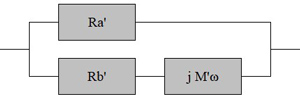
In some versions of the software (used by ITS human rssource i.e. for "internal use" mode), it is possible to model cloths (facings) as series elements (based on an electro-acoustic analogy), as previously described, while also accounting for their elasticity[4]; this is particularly useful for the design of hybrid resonators[3].
Thus, for "external use" specifically regarding each surfacing layer with index i ≤ imax the input data to be entered into the "in-COALA" Excel sheet are:
- a material reference (selected from the appropriate drop-down menu) and, if (and only if) the selected reference is BYOa or BYOb (Bring Your Own), the intrinsic parameters appropriate for the general acoustic behavior model being considered (FRO) i.e. airflow resistance (Ra'), surface mass (M"), and additional resistance (Rb')+
- a binary indicator (0/1) for inclusion
- a thickness - the temperature used is that of the porous medium of the specific set being considered, with the value chosen by the user -
- a model for the temperature dependence of airflow resistivity/airflow resistance, which applies to both the porous medium and the cloth (facing) of a given set
Of course, if the user has all the necessary input data, a cloth (facing) can alternatively (i.e. without being treated as a series element in an electro-acoustic analogy) be modeled using SILDIS® software as a porous medium (employing the JKD general acoustic behavior model), but in this case, the effect of its surface mass will not be taken into account.
Accounting for perforated protections using SILDIS® software for the modeling and optimization of multilayer acoustic structures
The intrinsic characteristics of perforated facings that can be accounted for in the SILDIS® software are: the hole diameter or side length (for square holes) / slot width (w) - and for slots only, the center-to-center spacing (e) - and the perforation rate, i.e. porosity (ε).
Using an electrical analogy, a perforated protection is treated as a series impedance.
Various models characterizing the acoustic behavior of perforated proections are implemented.
In the software versions generally marketed by ITS (i.e. for "external use"), regarding the general models for the acoustic behavior of perforated protections, at a minimum:
- at least one general model (e.g. DYM, L&C general models)
- is applicable only to circular perforations
- does not account for adjacent porous media when calculating impedance
- does not account for the velocity of any grazing flow when calculating impedance
- one general model (FRO general model):
- is applicable not only to circular perforations but also to other geometries, with various sub-models available to account for added length at the front and/or rear (sub-models C-REY3, Q-ALL, L-MEC1, BYO1, BYO2) in order to reflect the relevant thermo-viscous phenomena
- accounts for the adjacent rear porous medium when calculating impedance
- accounts for the velocity of any eventual grazing flow at the front (where applicable: for the upstream atmosphere) when calculating impedance
Summary of general models for the acoustic behavior of perforated protections in SILDIS® software for "external use"
| General model | DYM | L&C | FRO |
| Parameters (in addition to frequency and thickness) |
w (m)
|
w (m) |
w (m) |
| Perforations geometry | circular | circular | circular, square, or in the form of slits |
| Comment(s) |
properties of the rear porous medium not taken into account for the impedance calculation |
properties of the rear porous medium not taken into account for the impedance calculation velocity of any grazing flow not taken into account |
properties of the rear porous medium taken into account for the impedance calculation |
Summary of added length sub models for general model FRO for the acoustic behavior of perforated protections in SILDIS® software for "external use"
| Sub model of added length for general model FRO | C-REY | Q-ALL | L-MEC1 | BYO1 | BYO2 |
| Perforations geometry | circular | square | circular, square or in the form of slits | corresponding to user's input | corresponding to user's input |
Figure 7 illustrates the perforation geometries of the perforated plates for which calculations are possible using the FRO model.
   
Figure 7 geometry and added-length sub-models for perforated plates (in order of display): circular (orthogonal or hexagonal arrangement: sub-model C-REY3, square: sub-model Q-ALL, or slotted: sub-model L-MEC-1 considered with SILDIS® software in "external mode") |
Thus, for "external use", specifically regarding each perforated protection layer with index i ≤ imax, the input data to be entered into the "in-COALA" Excel sheet are:
- a material reference (selected from the appropriate drop-down menu) and, if (and only if) the selected reference is BYOa or BYOb (Bring Your Own), the intrinsic parameters appropriate for the general acoustic behavior model being considered i.e. the hole diameter or side length (if square) / slot width (w) - and, in the case of slots only, the spacing (pitch) - and the perforation rate i.e., the porosity (ε)
- a general acoustic behavior model and, if (and only if) the selected general behavior model is FRO:
- a sub-model for front and rear added length
- a grazing flow velocity value (Vg) and a grazing flow velocity limit value (Vglim) above which the front added length is no longer taken into account
- a binary indicator (0/1) for inclusion in the calculation
- a thickness - the temperature used is that of the porous medium of the assembly (set) in question, with the specific temperature value chosen by the user -
Accounting for thin plates using SILDIS® software for the modeling and optimization of multilayer acoustic structures
The intrinsic properties of thin plates that can be accounted for by the SILDIS® software include, at a minimum: Young's modulus (i.e. modulus of elasticity, E), density (ρ), Poisson's ratio (ν), and the loss factor (η).
In some versions of the software (used by ITS human ressource, i.e. for "internal use") and also in some of the software versions marketed by ITS (i.e. for "external use"), various types of thin plates can be taken into account:
- ordinary thin plates (i.e. neither perforated, laminated, nor orthotropic) (PL) cf. figure 8
- perforated thin plates (PERF) cf. figure 8
- laminated thin plates (2-PLY, 3-PLY) cf. figure 9
- orthotropic thin plates (COR, RIB, CLA) cf. figure 10
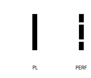
Figure 8 Geometry of single-layer thin plates that can be modeled using the SILDIS® software (from left to right): solid plate (PL) or perforated plate (PERF) |
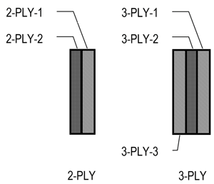
Figure 9 Geometry of multilayer plates modeled using SILDIS® software (from left to right): two-layer (2-PLY) or three-layer (3-PLY) |
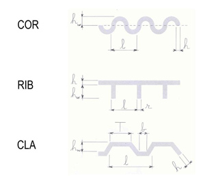
Fig. 10 Geometry of corrugations in orthotropic thin plates that can be modeled using SILDIS® software – from top to bottom: with sinusoidal corrugations (COR), with transverse stiffeners = ribbed plate (RIB), with trapezoidal corrugations (e.g.cladding) |
Summary of sub-models for laminated thin plates (with damping) 2-PLY in "in-out CODAP" Excel worksheet in SILDIS® software for "external use"
| Parameter | Young's modulus i.e. modulus of elasticity (E) | Poisson's factor (ν) | Loss factor (η) |
| Sub-model |
BER |
BASE i.e. that of the base plate |
BER MOI AB |
Summary of sub-models for laminated thin plates (with damping) 3-PLY in "in-out CODAP" Excel worksheet in SILDIS® software for "external use"
| Parameter | Flexural rigidity EI |
| Sub-model |
BER
|
Summary of sub-models for orthotropic plates in "in-out COORTP" Excel worksheet in SILDIS® software for "external use"
| Sub-model of orthotropic plate | COR | RIB | CLA | MOI |
| Nature of orthotropy | sinusoidal corrugation | transverses stiffeners = ribbed plate | trapézoidal ondulations (e.g. cladding) | undefined, the thin plate being characterized not by its detailed geometry but by a surface mass, a total thickness, and stiffness indicators |
| Parameters |
hw i.e. height of corrugations (m) |
hw i.e. height of stiffeners (m) |
hw i.e. height of corrugations (m)
|
M''' i.e. mass density (kg/m2)
|
| Comment(s) |
none |
none |
models of maximum bending stiffness possible: SAY, HAN |
none
|
Using an electrical analogy, a stack of thin plates placed against one another without bonding is treated as a series impedance.
In some versions of the software (used by ITS human ressource, i.e. for "internal use") and also in the software versions generally marketed by ITS (i.e. for "external use"), regarding general models of thin plates acoustic behavior, only a single (generalized) model is available, applicable to various types of thin plates mentioned above (when not ordinary: using concept of equivalent plates of which properties are computed as detailed above) with the exception of specific computations of which results (if available with the considered version of the Module 2 of SILDIS® software) are displayed in Excel worksheets "in-out COPPA1" and "in-out COPPA2". Sub-models allow for modeling variations regarding the loss factor and the effective critical frequency where or the speed of the free bending waves in the plate equals the speed of sound in the surrounding porous medium (fluid).
Summary of sub-models for loss factor and effective critical frequency of thin plates in "in-COALA" Excel sheet in SILDIS® software for "internal use" and "external use"
| Parameter | Loss factor (ν) | Effective critical frequency fc |
| Sub-model |
INT i.e. without empirical correction |
GER i.e. with empirical correction (depending on frequency) |
Thus, for "internal use" as for "external use", specifically regarding each thin-plate layer with index i ≤ imax, the input data to be entered into the "in-COALA" Excel sheet (and, where applicable - for some special plates - into other related sheets) are:
- a material reference (selected from the appropriate drop-down menu) and:
- for an ordinary plate (i.e. neither perforated, nor laminated, nor orthotropic): if (and only if) the selected reference is BYOa or BYOb (Bring Your Own), the intrinsic parameters appropriate for the general acoustic behavior model being considered (i.e. Young's modulus aka modulus of elasticity (E), density (ρ), Poisson's ratio (ν), and loss factor (η)); data entry is performed directly in the "in-COALA" Excel worksheet
- for a perforated plate: the intrinsic parameters appropriate for the general acoustic behavior model being considered, as for an ordinary plate (cf. above), plus the perforation rate (i.e. porosity (ε)) and the hole diameter or side length (if square) or slot width (w); data entry is performed not in the "in-COALA" Excel worksheet but in the "in-out COPERF" sheet and, if a library of materials equivalent to thin plates is included in the available software version, the PERFO material reference can be selected from a drop-down menu in the "in-COALA" Excel worksheet (otherwise, the output data from the "in-out COPERF" worksheet for the equivalent PERFO plate can be entered into the "in-COALA" Excel worksheet using the BYO reference)
- for a laminated plate (with a damping layer): the intrinsic parameters appropriate for the general acoustic behavior model, as considered for an ordinary plate (cf. above), for each sub-layer (1 base plate + 1 damping material for a 2-PLY thin plate, 1 base plate + 1 damping material + 1 constraining plate for a 3-PLY thin plate), as well as the thickness of each sub-layer (2 sub-layers for the 2-PLY thin plate and 3 sub-layers for the 3-PLY thin plate); data entry is performed not in the "in-COALA" Excel worksheet but in the "in-out CODAP" Excel worksheet, and, provided a library of materials equivalent to thin plates is included in the available software version:
- the 2-PLY material reference can be selected from a drop-down menu in the "in-COALA" Excel sheet for the two-layer assembly (alternatively, output data from the "in-out PERF" Excel worksheet for the equivalent 2-PLY plate can be entered into the "in-COALA" Excel worksheet using the BYO reference)
- the 3-PLY material reference can be selected from a drop-down menu in the "in-COALA" Excel sheet for the three-layer assembly (alternatively, output data from the "in-out PERF" Excel worksheet for the equivalent 3-PLY plate cannot be entered into the "in-COALA" Excel worksheet using the BYO reference, as they are frequency-dependent)
- for an orthotropic plate: a general model of orthotropic plate, and also the intrinsic parameters appropriate for the general acoustic behavior model, as considered for an ordinary plate (cf. above), as well as other input data that vary depending on the nature of the orthotropy and the associated sub-model (COR, RIB, CLA, MOI); data entry is performed not in the "in-COALA" Excel worksheet but in the "in-out COORT" Excel worksheet; furthermore, if a library of materials comparable to thin plates is included in the provided software version, the ORTHO material reference can be selected from a drop-down menu in the "in-COALA" Excel worksheet (otherwise, the output data from the "in-out PERF" Excel sheet for the equivalent ORTHO plate cannot be entered into the "in-COALA" Excel worksheet for the BYO reference)
- a model selcection (in a drop down menu) for the loss factor and the effective critical frequency
- a binary indicator (0/1) for inclusion in the calculation
- a thickness - the temperature used is that of the porous medium of the assembly (set) in question, with the specific temperature value chosen by the user -
Furthermore, for both "internal use" and "external use", regarding specifically the thin-plate layer of set 0 (if included), the user can choose (via a toggle switch) to assign to it all the properties of the layer from set 1 or set 2, with the exception of the number of plates, which may differ depending on selected input.
Examples of the use of multilayer acoustic structures modeling and optimization with SILDIS® software
Examples of the use of modeling and optimization for multilayer acoustic structures with SILDIS® software can be found elsewhere on this website:
Regarding SILDIS® software Module 1 in general:
Routines and Excel sheets of the software for the Module 1
Predictive calculation of insertion loss and self-noise of dissipative silencers
Regarding SILDIS® software Module 2 in general:
Routines and Excel sheets of the software for the Module 2
Prediction of acoustic performance of plane partitions and walls - software SILDIS® Module 2 / 2+
Regarding other aspects related to the functionalities of various modules (listed below in descending order of age, based on publications existing as of September 2026):
Sound absorption/attenuation - Modeling of hybrid resonators with CAD software SILDIS®
Prediction of acoustic performance of plane partitions and walls - software SILDIS® Module 2 / 2+
Computation of silencers with alternate splitter baffles orientation
Acoustics - Boosting silencer performance with SILDIS® software
Design and calculations of high performance baffle (splitter) silencers
Noise attenuation - Cylindrical dissipative silencer with reduced pressure drop
Silencers - Modeling the acoustic behavior of curved absorbers
[0] Sound Impact Limitation - Design for Industrialized Solutions
[1] COALA is the English acronym for COmputation of Acoustic LAyers
[2] in "external mode": thermodynamic (operating) conditions considered for clean, dry air (temperature, pressure); in certain software versions (used internally at ITS, i.e. in "expert mode"), it is possible to consider a different fluid
[3] cf. article Sound absorption/attenuation - Modeling of hybrid resonators with CAD software SILDIS®
[4] in some software versions (used internally at ITS, i.e. in "expert mode"), it is possible to assign thin-plate properties to surfaces, taking into account mounting conditions (free or clamped), geometry (rectangular or circular), and dimensions
 |
|