General information regarding the predictive calculation of insertion loss of dissipative silencers using SILDIS software
Module 1 of the SILDIS[0] software (in Excel format) enables the predictive calculation of insertion loss and self-noise (generated by the flow of the transported fluid) of dissipative silencers i.e. silencers whose effectiveness relies on a sound-absorbing lining.
For such devices reducing acoustic transmission within a duct, pipe, or opening (without obstructing fluid flow), the acoustic performance of dissipative (absorption-based) silencers is usually expressed as the difference between two sound power levels usually stated in dB ref. 1 pW (using the notation found in the SILDIS software):
- Lw0 without the silencer ("with zero silencer"), which is an input for the calculations
- Lw1 with the silencer ("with 1 silencer"), calculated using the formula Lw1 = 10 · log [10^(0.1 · (Lw0 - Di’)) + 10^(0.1 · Lw)]; where Di' is the insertion loss without consideration of self-noise (in dB) and Lw is the sound power level of the noise generated by fluid flow (self-noise) in dB rer. 1 pW
The insertion loss accounting for self-noise, Di, is calculated using the relationship Di = Lw0 - Lw1 (expressed in dB).
Calculations are performed across the 20 Hz - 20 kHz frequency range using 1/21-octave frequency bands, which form the basis for the displayed curves. Values for one-third-octave bands (center frequencies from 20 Hz to 20 kHz) and octave bands (center frequencies from 31.5 Hz to 16 kHz) are presented in tabular form. The A-weighted overall values - expressed in dB(A) - are calculated relative to the reference spectrum (Lw0, selected by the user and entered in 1/3-octave or octave bands in the "in COALA" Excel sheet).
Main aspects of the predictive calculation of dissipative silencer insertion loss using SILDIS software
The SILDIS software enables the predictive calculation of the insertion loss of dissipative silencers featuring sound-absorbing lining that may combine porous media, cloths (facings), and perforated protections. Another page on this site[1] provides detailed information regarding:
- the characteristics considered for each material layer (nature, model(s), thickness, temperature)
- the properties of the upstream atmosphere (fluid in the air passages) and the downstream conditions, depending on whether the simulation concerns (noting that no distinction arises in the case of plane acoustic waves: cf. Figure 1):
- half-splitter: it comes to plane of symmetry
- an extreme (end) splitter baffle or sound-absorbing lining mounted against the silencer casing: it comes to an impervious rigid wall
- the software's modeling capabilities
- the naming conventions for Excel sheets used for data input, output visualization (e.g. calculation results), or both tasks combined
- the "internal use" or "external use" operating modes
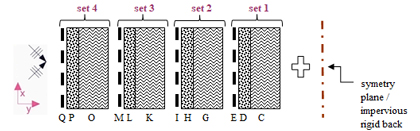
Figure 1 Multilayer acoustic structure with an impervious rigid back or a rear plane of symmetry, modeled using SILDIS software to predict dissipative i.e. abssorption-based silencers insertion loss; the model may include porous media (layers C, G, K, O, e.g., mineral wools or foams), cloths i.e. facings (layers D, H, L, P, e.g. glass veils, needle-punched felts, fabrics), and perforated protections (layers E, I, M, Q, e.g. perforated plates); in certain versions of the software, some cloth i.e. facings and perforated protective layers i.e. perforated protective layers can be accounted for as porous media. |
Thus, for both "internal use" and "external use," the input data to be entered are:
- in the "in-COALA" Excel sheet (and, where applicable - for certain special plates - into other related sheets): characteristics and properties listed above, and also the frequency spectrum of the noise to be attenuated i.e. the sound power Level Lw0
Computation-scheme (block-diagram) for the predictive calculation of insertion loss and self-noise of dissipative silencers using SILDIS software
The computation scheme (block digram aka functional diagram for the predictive calculation of the insertion loss and self-noise of dissipative silencers using SILDIS software is as shown in Figure 2 for the case of a locally reacting sound absorbing lining material:
- that is, assuming there is no sound transmission within the absorber (i.e. the sound-absorbing lining) in the direction of flow
- otherwise, the functional diagram remains valid with one exception: it differs regarding step [E], as evaluating surface impedance alone is insufficient and must be replaced by calculations based on more complex acoustic absorption functions
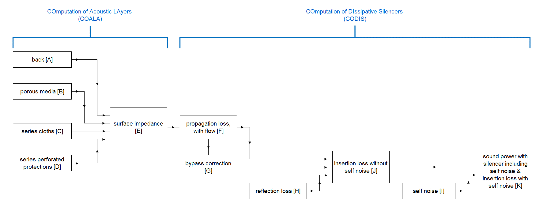
Figure 2 Functional diagram for the predictive calculation of insertion loss and self-noise of dissipative silencers using SILDIS software
The software enables performance simulations and sizing calculations for various combinations of acoustic structures and air passages (depending on the silencer's cross-section), referred to as "mountings." This term - used since time immemorial during the programming of the SILDIS software and the drafting of related documentation, and thus retained for the sake of overall consistency, including with regard to current and future additions - should be understood as meaning "configurations".
For all moutings, data entry - with the exception of thermodynamic conditions, of material layer data for the acoustic structure and of noise level to be attenuated (entered in the "in-COALA" Excel worksheet) and with one other exception - is centralized in the "in COSIL" Excel sheet. Results are displayed in a dedicated "in-out CODISx" Excel sheet, where x = 1, 2, 4, or 6 depending on the software version (in this latter Excel worksheet is entered a sound propagation condition model, constituting the aforementioned exception).
|
Figure 3 Overview of the Excel spreadsheets involved in dissipative silencer calculations using Module 1 of the SILDIS software, for "external use" |
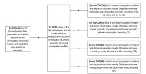
Summary of Excel sheets (in addition to the "in COSIL" Excel work sheet) dedicated to the various mountings for predicting insertion loss and self-noise (caused by fluid flow) in dissipative silencers for "external use," depending on the software version (Table 1)
| Excel worksheet | in-out CODIS1 | in-out CODIS2 | in-out CODIS4 | in-out CODIS6 |
| Cross-section & mountings | for rectangular cross-section with symmetrical packing (mountings R, R"), and (with performance extrapolated from that for rectangular section with symmetrical packing): for circular cross-section with concentric rings (mountings C1½, C2, C2½, C3, C3½) or with transverse baffles (mounting CR) | with performance extrapolated from that for a rectangular cross-section: square cross-section (mounting Q) or circular cross-section without central splitter (mounting C0) | (calculation involving Bessel functions) circular cross-section with central splitter (mounting C1A) | for rectangular section assemblies (RA), with asymmetric packing |
| Sets included in the acoustic structure | sets with index i to imax | sets with index i to imax |
set 1 (for the ring) and set 2 (for the central splitter) |
set 1 and set 2 |
Figure 4 below illustrates the various mountings for which performance simulations are possible for "external use," depending on the software version
Mountings of the "in-out CODIS1" Excel worksheet (depending on the software version)
mounting R" |
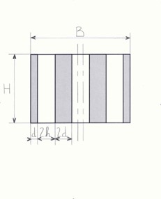
mounting R |
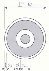
mounting C1½ |
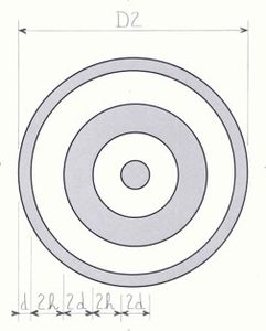
mounting C2 |
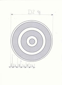
mounting C2½ |
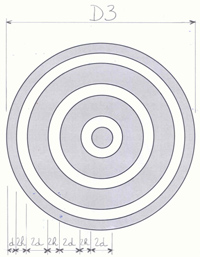
mounting C3 |
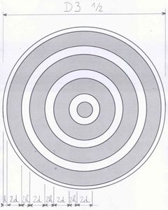
mounting C3½ |
mounting CR |
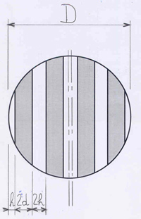
Mountings of the "in-out CODIS2" Excel work sheet (depending on the software version)
|
mounting Q |
mounting C0 |
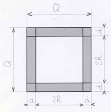
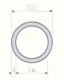
Mountings of the "in-out CODIS1" Excel worksheet (depending on the software version)
|
mounting C1A |
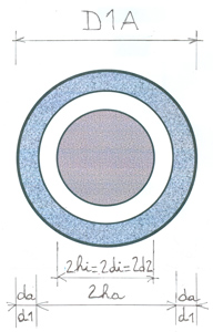
Mountings of the "in-out CODIS6" Excel worksheet (depending on the software version)
|
mounting RA |
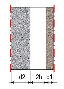
Figure 4 - mountings for which performance simulations are possible for "external use," depending on the software version in question
Geometry and sound propagation conditions considered for the predictive calculation of insertion loss and self-noise of dissipative silencers using SILDIS software
The geometry considered for the predictive calculation of insertion loss and self-noise in dissipative silencers using SILDIS software involves two main axes:
- x: in the direction of flow (the direction in which noise attenuation is sought)
- y: in the direction perpendicular to the sound-absorbing lining surface (which may be flat or curved)
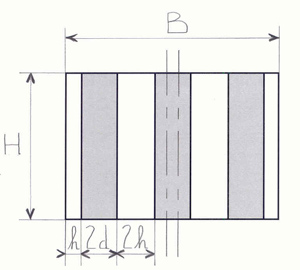
In the specific case of a rectangular-section silencer, a third axis is considered (z: perpendicular to the other two), with the geometry used then being illustrated in Figure 5.
|
Figure 5 Geometric parameters for the predictive calculation of insertion loss and self-noise (generated by the flow of the transported fluid) of dissipative silencers with rectangular splitter baffles using SILDIS software |
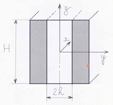
For all configurations i.e. possibly for the Excel sheets "in-out CODIS1," "in-out CODIS2," "in-out CODIS4," and "in-out CODIS6" (depending on the software version):
Dimensions related to silencer length (L, regardless of the suffix) are measured along the x-axis.
Dimensions related to material thicknesses (d, regardless of the suffix) and dimensions relating to air ways (h, regardless of the suffix) are measured along the y-axis:
- d (regardless of the suffix) refers to the overall thickness of a sound absorbing lining either with a rear plane of symmetry or an impervious rigid back rigid back
- 2d (regardless of the suffix) refers to the overall thickness of a splitter baffle (consisting of two half-splitters placed back-to-back)
With reference to the x and y directions defined above, sound propagates within the sound- absorbing lining of a dissipative silencer along the y-axis (a phenomenon accounted for by the SILDIS software across all sound propagation scenarios - two for "external use" and three for "internal use" - listed below):
- this propagation depends on σy, the airflow resistivity of the sound-absorbing lining in the y-direction
- the sound attenuation of a dissipative silencer always depends on this phenomenon; without it, there is no performance (beware of linings that are too airtight !)
For "external use," two conditions regarding acoustic wave propagation within the sound-absorbing lining in the x-direction are considered (where σx is the flow resistivity of the sound-absorbing lining in the x-direction):
- locally reacting absorber: the notation σx/σy=∞ symbolizes the absence (actual or assumed) of sound propagation within the absorbing lining in the x-direction; in practice - aside from the case of a material with very high flow resistivity in the x-direction (σx) - this corresponds to the presence of transverse partitions made of sufficiently thick sheet metal (spaced at sufficiently short intervals - there is no consensus on this: is it less than a quarter, or even a sixth, of the wavelength corresponding to the frequency in question ?) that block noise transmission within the sound-absorbing lining in the direction of flow
- homogeneous (isotropic) absorber: the notation σx/σy=1 symbolizes the existence of sound propagation within the absorbing lining in the x-direction, based on the assumption of homogeneity (i.e. having the same properties in both the x and y directions)
For "internal use," a third condition regarding acoustic wave propagation is considered:
- anisotropic absorber: the notation σx/σy=var. (abbreviation for "variable") symbolizes the existence of sound propagation in the x direction within the sound-absorbing lining, which has different properties in the x and y directions
Considerations regarding material thicknesses for the predictive calculation of insertion loss and self-noise of dissipative silencers using SILDIS software
For an "external use," the following settings should be considered:
- maximum set index imax = 1; imax: as defined elsewhere on this site[1] and to be entered in the "in COALA" Excel worksheet
- limit set index ilim = 1; this index is specific to calculations involving dissipative silencers, defining the set upstream of which material layers are modeled - using an electro-acoustic analogy- as a series impedance (even when involving porous media), and is to be entered in the "in COSIL" Excel worksheet
- the definition of thicknesses depends on the considered mounting
For all configurations in the "in-out CODIS1" and "in-out CODIS2" Excel sheets (depending on the software version)
For the total thickness d of the considered acoustic structure (depending on the case: sound-absorbing lining with an impervious rigid back, or a half-splitter baffle with a plane of symmetry at the rear), the following formula applies:
|
Formula 1 |
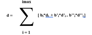
Where (selected by user):
di (resp. d’i, d’’i): thickness of the porous medium (resp. of the cloth aka facing layer, of the perforated protection aka perforated protective layer) of set i
bi (resp. b’i, b’’i) = 0 or 1 (binary indicator) depending on whether or not the element in question from set i is incorporated into the acoustic structure
imax: maximum set index; imax: as defined elsewhere on this site[1] and to be entered in the "in COALA" Excel worksheet
dlocal = dbulk = thickness of the porous medium of set 1
dlocal thus complies with the general definition illustrated by Formula 2 below (superfluous for "external use"):
|
Formula 2 |
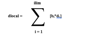
Where (selected by user): di: thickness of the porous medium in set i bi = 0 or 1 (binary indicator) depending on whether or not the element in question from set i is incorporated into the acoustic structure
ilim: as defined above
For the mounting C1A in the "in-out CODIS4" Excel sheet (depending on the software version):
The total thickness of the acoustic structure in question is:
- da for the ring with sound-absorbing lining: the total thickness of set 1
- di for the overall diameter of the solid central splitter: the total thickness of set 2
dalocal = thickness of the porous medium of set 1
dilocal = thickness of the porous medium of set 2
For the mouting RA in the "in-out CODIS6" Excel sheet (depending on the software version):
The total thickness of the acoustic structure in question is:
- d: the average of the total thickness of set 1 and the total thickness of set 2
dlocal = dbulk = the average of the thickness of the porous medium in set 1 and the thickness of the porous medium in set 2
Considerations regarding air passage dimensions for the predictive calculation of insertion loss and self-generated noise of dissipative silencers using SILDIS software
For "external use," the following settings should be considered:
- the definition of air channel dimensions depends on the considered mounting
For all configurations in the "in-out CODIS1" Excel sheet and for configuration Q in the "in-out CODIS2" Excel sheet (depending on the software version):
- for all configurations in the "in-out CODIS1" Excel sheet, h is the dimension (in the aerolic sense, i.e. related to the clear opening for the conveyed fluid) of an end air channel of the silencer - in the y-direction, between a splitter baffle and the casing -, and 2h is the dimension (in terms of airflow, i.e. related to the clear opening for the conveyed fluid) of a channel between two splitters baffles
- for configuration Q in the "in-out CODIS2" Excel sheet, 2h is the dimension (in the aerolic sense, i.e. related to the clear opening for the conveyed fluid) between facing sound-absorbing linings
- hlocal = d + h - dlocal ; hbulk = d + h - dbulk
For configuration C0 in the "in-out CODIS2" Excel sheet (depending on the software version):
- 2a is the dimension (in the aerolic sense, i.e. related to the clear opening for the conveyed fluid) between facing sound-absorbing linings, i.e. the clear passage diameter
- alocal = d + a – dlocal ; abulk = d + a – dbulk
For the C1A assembly in the "in-out CODIS4" Excel sheet (depending on the software version):
- (reminder) da=d1 is the total thickness of the ring with sound-absorbing lining (this is the total thickness of set 1)
- 2ha is the inner diameter of the ring with sound-absorbing lining (in the aerolic sense, i.e. related to the clear opening for the conveyed fluid)
- 2hi=2di=2d2 is the overall diameter of the solid central splitter (reminder: this is the total thickness of set 2)
- ha - hi is the dimension (in the aerolic sense, i.e. related to the clear opening for the conveyed fluid) between facing sound-absorbing linings
- halocal = da + ha - dalocal hilocal = di + hi - dilocal
For the RA assembly in the "in-out CODIS6" Excel sheet (depending on the software version):
- 2h is the dimension (in the aerolic sense, i.e. related to the clear opening for the conveyed fluid) of an air passage between 2 splitter baffles
- hlocal = d + h - dlocal ; hbulk = d + h - dbulk
Considerations regarding the prediction of insertion loss for dissipative silencers using SILDIS software
Insertion loss, excluding self-noise (Di’ in dB), is calculated using the general formula Di’ = Da.L + Dc + Dr (dB)
In the above:
- Da: propagation loss (dB/m); the performance (Da.L) that would be obtained if it were purey and simply proportional to the length L
- Dc: by-pass i.e. flanking transmission correction (dB); accounting for unwanted sound transmission
- Dr: reflection loss (dB); resulting - where applicable - from the change in cross-section at the silencer inlet and outlet
- L: silencer length (m)
Input data for the predictive calculation of insertion loss and self-noise of dissipative silencers using SILDIS software
The input data for calculating the predicted insertion loss and self-noise of dissipative silencers using the SILDIS software must be entered into three different Excel sheets:
- in the "in COALA" Excel sheet:
- (as described on another page of this site[1]) regarding the thermodynamic conditions of the conveyed fluid, the characteristics (nature, temperature, modeling elements) of the layers of the acoustic structure under consideration, and the nature of what is at the rear (a choice between a symmetry plane and an impervious rigid back must be made)
- the spectrum of the noise to be attenuated (sound power level Lw0)
- for "external use," in the specific context of simulating noise attenuation using silencers, a maximum set index imax = 1
- in the "in COSIL" Excel sheet, in the left-hand part of the table - data common to several (if not all) configurations -:
- for "external use," a limit set index ilim = 1
- the value of parameter h related to the flow passage dimension of the conveyed fluid
- used directly for the configurations in the "in-out CODIS1" and "in-out CODIS6" Excel sheets and for configuration Q in the "in-out CODIS2" Excel sheet
- enabling the calculation of radius a for configuration C0 in the "in-out CODIS2" Excel sheet
- unused for the "in-out CODIS4" Excel sheet; the flow passage dimension is not an input parameter, but the result of subtracting two user-selected diameters
- the mass flow rate value (displaying the fluid density allows - where useful - this input parameter to be calculated when only the volumetric flow rate is explicitly known)
- a model selection for the bypass correction (Dc) and a silencer length (LDc) above which it is applied (being zero below this length)
- a model selection for the reflection loss (Dr)
- in the "in COSIL" Excel sheet, in the right-hand section of the table: specific data for each of the configurations considered in the "in-out CODIS1", "in-out CODIS2", "in-out CODIS4", and "in-out CODIS6" Excel sheets (depending on the software version)
- a general model for flow-generated sound power (to calculate a single, overall value for clean, dry air at ambient conditions) Lwa (dB)
- a model for thermodynamic correction (to adjust this value based on fluid characteristics at operating conditions) C1 (dB)
- a model for spectral correction (to obtain levels for the various frequency bands) C2 (dB)
- in the "in CODISx" Excel sheet - where x = 1, 2, 4, or 6, depending on the software version -
- for an external use": the sound propagation condition
Summary of models common to several (if not all) mountings to be entered into the "in COSIL" Excel sheet for the predictive calculation of insertion loss and self-noise (due to the flow of the conveyed fluid) of dissipative silencers for "external use," depending on the software version (Table 2)
| Parameter | Models |
| By-pass correction (Dc) |
FRO1 for the mountings in the "in-out CODIS1" Excel sheet, at ambient conditions - e.g. for comparison with laboratory testing results |
| Reflexion loss (Dr) |
MUL for moutings other than Q and C0: at ambient conditions, e.g. for comparison with laboratory testing results |
For an "external use", the recommended model(s) are those both underlined and shown in bold in the table above.
The sound power level of the self noise (due to the flow) is calculated per octave frequency band using the formula Lw = Lwa + C1 + C2 (dB), with Lwa, C1, and C2 as defined above.
Summary of specific models for each configuration considered in the "in-out CODIS1", "in-out CODIS2", "in-out CODIS4", and "in-out CODIS6" Excel sheets (depending on the software version), to be entered into the "in COSIL" Excel sheet for the predictive calculation of self-generated noise (caused by the flow of the transported fluid) in dissipative silencers, for "external use," depending on the software version (Table 3)
| In the Excel worksheet "in COSIL", for the mountings of the dedicated Excel worksheet | in-out CODIS1 | in-out CODIS2 | in-out CODIS4 | in-out CODIS6 |
| General models for flow-generated sound (acoustic) power (Lwa) | 2081a 2081b 2081c 2081d 2081d* 2081e 2081e* 2567 11463 |
2081a |
2081a 2081b 2081c 2081d 2081d* 2081e 2081e* |
2081a 2081b 2081c 2081d 2081d* 2081e 2081e* 2567 11463 |
| Models for thermodynamic correction (C1) | 3733a 3733b 3733c for conditions other than ambient ZER i.e. ZERo: for ambient conditions |
3733a 3733b 3733c for conditions other than ambient ZER i.e. ZERo: for ambient conditions |
3733a 3733b 3733c for conditions other than ambient ZER i.e. ZERo: for ambient conditions |
3733a 3733b 3733c for conditions other than ambient ZER i.e. ZERo: for ambient conditions |
| Models for spectral correction (C2) | 2081a 2081b 2081c 2081d 2081e 3733a 3733b 3733c |
2081a 2081b 2081c 2081d 2081e 3733a 3733b 3733c |
2081a 2081b 2081c 2081d 2081e 3733a 3733b 3733c |
2081a 2081b 2081c 2081d 2081e 3733a 3733b 3733c |
For an "external use", the recommended model(s) are those both underlined and shown in bold in the table above.
Summary of specific models for each configuration considered in the "in-out CODIS1", "in-out CODIS2", "in-out CODIS4", and "in-out CODIS6" Excel worksheets (depending on the software version), to be entered into these sheets for the predictive calculation of insertion loss and self-generated noise (due to the flow of the transported fluid) for dissipative silencers intended for "external use" (Table 4).
| Excel worksheet | in-out CODIS1 | in-out CODIS2 | in-out CODIS4 | in-out CODIS6 |
| Models for sound propagation |
σx/σy=∞ locally reacting absorber |
σx/σy=∞ locally reacting absorber σx/σy=1 homogen absorber |
σx/σy=∞ locally reacting absorber |
σx/σy=∞ locally reacting absorbers σx/σy=1 homogen absorbers |
For an "external use", the recommended model(s) are those both underlined and shown in bold in the table above.
Results of the predictive calculation of insertion loss and self-noise calculation of dissipative silencers using SILDIS software
The results obtained from predicting the insertion loss and self-noise of dissipative silencers using SILDIS software are:
- comparable to standardized measurements i.e. ISO 7235, which specifies laboratory measurement procedures for ducted silencers and terminal units (for case studies involving air at ambient temperature and pressure)
- suitable for case studies involving much more demanding sizing requirements
- complemented by an assessment of total pressure loss (as outlined in the aforementioned standard), which characterizes aerodynamic performance, going hand in hand with acoustic performance when evaluating the pros and cons of a silencer design, as soon as flow rate is not zero
For all mountings i.e. possibly for the "in-out CODIS1", "in-out CODIS2", "in-out CODIS4", and "in-out CODIS6" Excel sheets (depending on the software version)
The main output data are as follows:
- insertion loss with airflow, excluding self-generated noise, Di' (cf. Figures 6, 7, 9)
- curves, graphs, and tables: per 1/3-octave and 1/1-octave frequency bands (as well as A-weighted overall value, calculated relative to the reference noise spectrum Lw0)
- self-generated noise (sound power level of flow-induced noise)
- graphs and tables: per 1/1-octave frequency bands (as well as A-weighted overall value)
- sound power level with silencer Lw1 (see Figure 8)
- graphs and tables: per 1/1-octave frequency bands (as well as A-weighted overall value)
- insertion loss with airflow, including self-generated noise, Di (see Figure 9)
- curves, graphs, and tables: per 1/1-octave frequency bands (as well as A-weighted overall value, calculated relative to the reference noise spectrum Lw0)
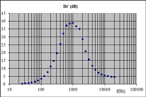
Figure 6 Insertion loss of a silencer without self-noise, i.e. without flow-generated noise Di' (curve) |
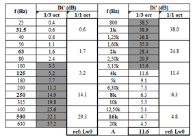
Figure 7 Insertion loss of a silencer without self-noise, i.e. without flow noise Di' (table) |
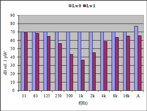
Figure 8 Sound power level without or with a silencer, denoted Lw0 and Lw1, respectively' |
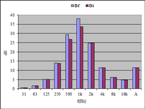
Figure 9 Insertion loss of a silencer with or without consideration of flow noise (i.e. self-generated noise), denoted Di and Di', respectively' |
To document in the best possible way acoustic performance in terms of insertion loss disregarding self-generated noise Di’ = Da.L + Dc + Dr (dB), additional output data are provided:
- propagation loss, i.e. longitudinal attenuation Da.L (cf. Figure 9)
- curves: narrow-band i.e. per 1/21 octave frequency band;graphs and tables: per 1/3-octave and 1/1-octave frequency bands (as well as A-weighted overall value, calculated relative to the reference noise spectrum Lw0)
- by-pass i.e. flanking transmission correction Dc (cf. Figure 10)
- graphs and tables: per 1/3-octave and 1/1-octave frequency bands (as well as A-weighted overall value, calculated relative to the reference noise spectrum Lw0)
- reflection loss Dr (cf. Figure 11)
- graphs and tables: by 1/3-octave and 1/1-octave frequency bands (as well as A-weighted overall value, calculated relative to the reference noise spectrum Lw0)
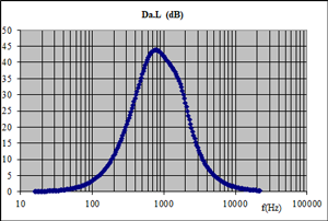
Figure 10 Silencer propagation loss Da.L |
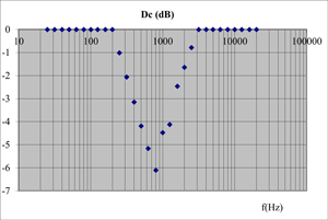
Figure 11 Silencer by-pass correction Dc |
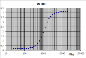
Figure 12 Silencer reflection loss |
[0] Sound Impact Limitation - Design for Industrialized Solutions
[1] cf. Modeling and optimization of multilayer acoustic structures using SILDIS software
 |
|