General information relating to noise attenuation and pressure drop of dissipative silencers
Whether in the construction sector, or for industrial applications, noise attenuation in fluid networks is often achieved using dissipative silencers. The power of the sound waves is then reduced (mainly) depending on the distance traveled along their path in the open channels i.e. the airways (with on the periphery - and/or in the form of splitters - a packing of sound absorbing material) and also (secondarily) at the inlet and outlet due to the change in the fluid passage section.
The complement to 1 (100%) of the free passage rate[1] for the fluid (which can be called blocking rate) is determining for the dimensioning of such noise reduction devices, since when it increases, also grow (all things being equal):
- acoustic performance (transmission loss, reflection loss, insertion loss)
- pressure drop (total pressure loss)
The first characteristic, which is sought (acoustic performance) can not be separated from the second, which it is desirable to limit (pressure drop), and a compromise must be found on a case-by-case basis.
The issues concerning the pressure drop of silencers vary depending on the context, with possibly:
- the need not to reduce the fluid flow too much in an aeraulic or pressurized fluid network (e.g. by maintaining the operating point of fans, pumps, compressors) in the Ventilation Heating Air Conditioning (HVAC) sector in general, with sometimes more demanding applications: ventilation systems for industrial enclosures and test benches, facilities with air coolers, cooling towers, chimneys (stacks)
- the need not to negatively impact a process (e.g. for intake and exhaust of engines or turbomachinery as well as downstream of valves) and in particular its efficiency, as well as its operating cost e.g. when it comes to thermal and/or electrical production
Evaluating sufficiently precisely and minimizing the pressure drop of a silencer is a recurring imperative for an acoustic engineer or a construction technician, especially as the fluid speed considered is high (since the total pressure loss is proportional to the square of this parameter)[2], just like evaluating sufficiently precisely and maximizing its acoustic performance.
In this regard, it should be borne in mind that, with regard to noise reduction, the effectiveness of a silencer cannot be judged by considering a single performance indicator (acoustic attenuation depends - often: a lot - on frequency), and that it is therefore difficult to formulate generalities when it comes to comparing the acoustic performance of different silencer concepts (the expression "- in general -" used in a such context in the rest of this article refers to this reality).
Noise attenuation and pressure drop of ordinary cylindrical dissipative silencers
For quite a long time, Module 1 of the SILDIS®[3] software allows the simulation of noise attenuation and pressure loss of cylindrical dissipative silencers[4] (such a geometry is of course particularly indicated when the upstream and/or downstream duct is itself with a circular section; it offers a fairly wide variety of possible combinations of airways and sub-assemblies constituting the sound-absorbing material filling) and various improvements have been made over time to its features in this domain[5][6] (e.g. for air conditioning or ventilation networks, for air intakes, exhaust lines of engines and combustion turbines, process chimney ducts).
The sound-absorbing filling (lining) can be taken into account in the form of a multi-layer acoustic structure, the number of sub-assemblies of which (each with a porous medium[7], possibly covered on the one hand with a surfacing[8] and on the other hand with a perforated protection[9]) is variable (from 1 to 4) depending on the considered assembly (cf. fig. 1)
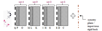
Figure 1 Multilayer acoustic structure (i.e. combination of materials) considered for predicting the acoustic performance of silencers with Module 1 of the SILDIS® software - C, G, K, O: porous medium[7] - D, H, L, P: surfacing[8] - E, I, M, Q: perforated protection[9] |
The functional calculation diagram for predicting the acoustic performance of silencers with Module 1 of the SILDIS® software is as illustrated in Figure 2 in the case of a filling made of a sound absorbing material being locally reacting[10].
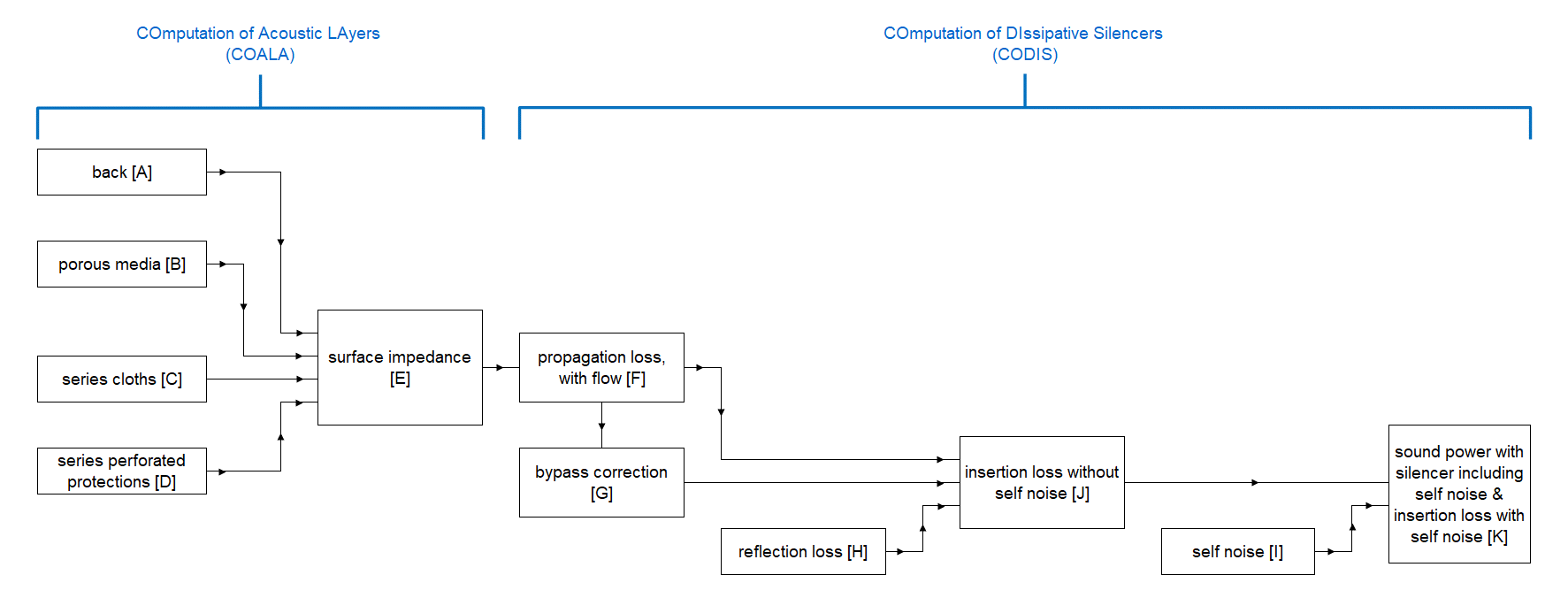
Figure 2 Functional calculation diagram for predicting the acoustic performance of silencers with Module 1 of the SILDIS® software in the case of a filling made of a sound absorbing material being locally reacting[10] |
- dissipative silencer with circular cross section without central pod (see fig. 3) - C0A assembly -
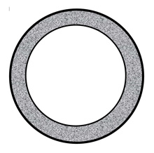
Figure 3 Dissipative silencer of circular section without central pod - C0A assembly -
The acoustic performance is evaluated using a specific calculation (analytical method involving Bessel and Neumann functions with complex argument) taking into account in particular:
- with regard to the sound-absorbing filling: a curved absorber model, possibly with the EDC layers of the multi-layer acoustic structure of Figure 1 i.e. with 1 porous medium[7], possibly covered on the one hand with a surfacing[8] and on the other hand a perforated protection[9] ; it is assumed that it is a locally reacting absorber[10]
- with regard to fluid speed: its influence on the propagation loss (depending on its value and its direction), and on the self noise linked to it (flow noise)
The aerodynamic performance is evaluated by taking into account in particular:
- the linear pressure drop variable with the roughness of the filling, like what is done for ordinary ducts
It can be noted that with module 1 of the SILDIS®[3] software, the performance of cylindrical dissipative silencers can also be calculated using the C0 assembly, which differs from the C0A assembly with regard to the calculation of the acoustic performance[11].
- dissipative silencer with circular cross section with solid or hollow central pod (sealed at both ends) (see fig. 4a and fig. 4b) - assembly C1A -
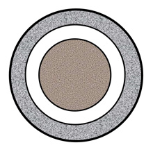
Figure 4a Dissipative silencer with circular section with solid central pod - C1A assembly -
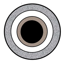
Figure 4b Dissipative silencer with circular section with hollow central separator (sealed at both ends) - C1A assembly -
The acoustic performance is evaluated using a specific calculation (analytical method involving Bessel and Neumann functions with complex argument) taking into account in particular:
- with regard to the sound-absorbing filling: a curved absorber model, possibly with the EDC layers of the multi-layer acoustic structure of Figure 1 i.e. with 1 porous medium[7], possibly covered on the one hand with a surfacing[8] and on the other hand a perforated protection[9]; it is assumed that it is a locally reacting absorber[10] ; this acoustic structure can be different for the central pod and for the annular lining
- with regard to the speed of the fluid: its influence on the self noise linked to it (flow noise)
The aerodynamic performance is evaluated by taking into account in particular:
- the linear pressure loss varies with the roughness of the filling, like what is done for ordinary ducts
- the singular pressure loss linked to the change of section at the inlet and outlet
In addition to the general case (when all thicknesses of sound-absorbing material are arbitrary but not zero), several particular cases of silencer geometry can be considered with the C1A assembly:
- a zero central pod diameter in Figure 4a: in this configuration, the C1A assembly is then equivalent to the C0A assembly
- a zero exterior peripheral annular sound-absorbing lining thickness in Figure 4b: in this configuration, the C1A assembly makes it possible, for example, to simulate the insertion of a central spilitter in a stack (chimney) duct to limit noise at outlet
- comments relating to the C0A and C1A assemblies
Compared to the C0A assembly, the C1A assembly has:- an acoustic performance (transmission loss, reflection loss, insertion loss) - in general - higher (that of the C0A assembly being by nature low, unless the sound absorbing surfaces facing each other are very close i.e. unless that the diameter of the circular fluid passage section is sufficiently small)
- a generally higher pressure drop (total pressure loss) ; this depends on the geometric parameters of C1A assembly, that of the C0A assembly being by nature low due to the absence of any obsacle along fluid path
The preference for one or the other assembly (without or with pod also referred to as cenral body or splitter) therefore depends on the constraints linked to each project and on sizing possibilities.
Noise attenuation by means of a cylindrical dissipative silencer with reduced pressure drop
Noise attenuation by means of a cylindrical dissipative silencer with reduced pressure loss (compared to that of the C1A assembly) presents the advantages mentioned above with regard to the generalities relating to the pressure loss of dissipative silencers, its interest potential being a priori all the greater as the reduction in its acoustic performance will be less.
- dissipative silencer with a circular cross section with hollow pod (central body) open at each end (see fig. 5) - assembly C1A+C0A -
From what was mentioned previously for the C0A and C1A assemblies, the configuration corresponding to a dissipative silencer with a circular section with hollow central pod open at each end - in the SILDIS® software nomenclature: C1A+C0A - can be considered in combining the C1A and C0A assemblies previously described.This involves nesting inside the central pod of the C1A assembly (which is - by definition - not necessarily full, although sealed at both ends, as illustrated in Figure 4b) the entire assembly C0A while removing the end seals of the latter (see fig. 5), both adjoining rigid and impervious backs of the two sub-assemblies C1A and C0A merging to make one (in practice: a very thick metal partition), which is the basis for the calculation of impedance of the acoustic structures with the desired rear boundary condition.
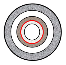
Figure 5 Cylindrical dissipative silencer with reduced pressure drop i.e. dissipative silencer with a circular cross section with hollow central pod open at both ends - C1A+C0A assembly -. In red: two rigid and impervious backs of the two subassemblies C1A and C0A which merge to make one ; beyond this limit: C1A assembly; below this limit: C0A assembly
Based on the separate calculations (performed simultaneously by the SILDIS® software, as mentioned previously: by means of analytical method involving the Bessel and Neumann functions with complex argument) corresponding to the C0A and C1A assemblies whose results are combined, the acoustic performance is evaluated taking into account in particular:
- with regard to the sound-absorbing filling: a curved absorber model, possibly with the EDC layers of the multi-layer acoustic structure of Figure 1 i.e. with 1 porous medium[7], possibly covered on the one hand with a surfacing[8] and on the other hand a perforated protection[9]; it is assumed that it is a locally reacting absorber[10]; this acoustic structure can be different for each of the three annular sound absorbing linings
- with regard to the fluid speed: its influence on the transmission loss (according to its value and its direction) only for the fluid passage section which is circular (it is therefore desirable that the Mach number in the annular section can be small enough for satisfactory accuracy of simulations); its influence on the self noise linked to it (flow noise)
The aerodynamic performance is evaluated by taking into account in particular:
- the linear pressure loss varies with the roughness of the filling, like what is done for ordinary ducts
- the singular pressure loss linked to the change of section at the inlet and outlet
- comments relating to the C1A and C1A+C0A assemblies
Compared to the C1A assembly, the C1A+C0A assembly has:- an acoustic performance (transmission loss, reflection loss, insertion loss) which can - in general - be kept sufficiently close to that of the C1A assembly when the sound absorbing surfaces facing each other at the level of the circular passage section of the fluid are sufficiently close ; this implies that the diameter of the circular fluid passage section, and then that the area of the corresponding fluid passage section is sufficiently small e.g. with respect to that of the annular passage section
- a pressure drop (total pressure loss) always lower, since in relation to the different terms of the formula allows the calculation of the pressure loss[2]:
- pressure loss coefficient is reduced
- average speed (possibly different in the circular section and in the annular section) is reduced
With regard to this double effect, even if the precise quantification of the first is difficult by an analytical method (due to the lack of specific experimental data base allowing a formulation by regression with geometric data as variables) - it is possible by a numerical method[12] -, just taking into account the second is sufficient to consider that a dissipative silencer of circular section with hollow central pod open at each end - C1A+C0A assembly - is with a reduced pressure loss (compared to that of the C1A assembly).
- overall
The SILDIS® [3]software allows the calculation of acoustic & aerodynamic performance of cylindrical dissipative silencers with reduced pressure loss i.e. dissipative silencers of circular section with hollow central pod open at each end (C1A+C0A assembly). (see fig. 6)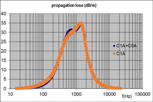
Figure 6 Acoustic performance of dissipative cylindrical silencers with central pod either full or hollow and then sealed at both ends - C1A assembly - or hollow and open at both ends - C1A+C0A assembly - with for each sound-absorbing material layer an equal reduced flow resistance equal to 3; no surfacing taken into account, no perforated protection taken into account; with, in the configuration considered, the advantage of the C1A+C0A assembly, being an increase (compared to the C1A assembly) of the free passage area of the fluid of 6.2% i.e. a reduction in the pressure loss of 12.8% (all other things being equal)
Improving the aerodynamic performance of such noise attenuation devices without degrading the acoustical performance and/or maintaining its overall size within an imposed limit are objectives which can be achieved from a competitive optimization perspective.
Used wisely, such a concept of cylindrical dissipative silencer with reduced pressure loss i.e. of dissipative silencer of circular section with hollow central pod open at each end is likely to allow varied applications in the building sector or in the context of industrial soundproofing projects, completing the range of assemblies for which such calculations can already be carried out with the SILDIS® software[3][13][14].
[1] ratio of the fluid passage area to the frontal area (taking into account the cumulative thickness of the absorbent filling layers)
[2] the total pressure loss can be calculated using the equation ΔP = ζ * 1/2 * ρ * V2 with ΔP = total pressure loss (Pa) ; ζ = total pressure loss coefficient ; ρ = fluid density (kg/m3) ; V = fluid speed (m/s)
[3] Sound Impact Limitation Design for Industrial Solutions (cf. https://www.its-acoustique.fr/en/acoustical-insulation-soundproofing/acoustic-aeraulic-construction-cad-calculation-software.html)
[4] cf. Prediction of acoustic and aerodynamic performance of silencers - software SILDIS® Module 1
[5] cf. Silencers - Modeling the acoustic behavior of curved absorbers
[7] characteristics taken into account: resistivity, porosity, tortuosity, thermal characteristic length, viscous characteristic length, density, thickness
[8] characteristics taken into account: airflow resistance, mass density, thickness
[9] characteristics taken into account: porosity, perforation geometry, mass density, thickness
[10] a local reaction means an absence of longitudinal sound propagation (i.e. no sound propagation in absorber in the flow direction) is assumed, whether it results from a sufficiently large resistance to the passage of air of the packing material, or from transverse partitions provided for purpose
[11] for the C0 assembly, the acoustic performance is evaluated by extrapolation of the acoustic performance corresponding to a square section duct (itself: twice that corresponding to a given thickness of sound absorbing material and airway distance for a duct with a rectangular cross section lined on two sides) taking into account in particular:
- with regard to the filling: a plane absorber model, possibly the entire multilayer acoustic structure of Figure 1 with, depending on the case, porous media[7], surfacings[8] perforated protections[9] ; it is not necessarily assumed that it is a local reaction absorber[10], the latter being able to be isotropic or anisotropic (for set 1 of the acoustic structure in Figure 1)
[13] dissipative silencer with a circular cross section - Cn assembly (with 1 solid central splitter and with n-1 concentric separators n= 1, 1 ½, 2, 2 ½, 3, 3 ½); the suffix ½ refers to the presence of an additional peripheral half airway; the absence of a suffix refers to a peripheral lining instead; assembly C3 is illustrated below (see fig. 7)[15]
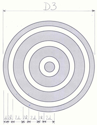
Figure 7 Dissipative silencer with a circular cross section - C3 assembly -(with 3 splitters: 1 central and 2 concentric, and with a peripheral sound-absorbing lining)
[14] dissipative silencer with a circular cross section with non-concentric (transverse) splitters (cf. fig. 8)[15]
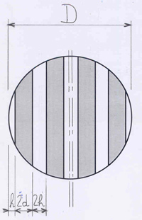
Figure 8 Dissipative silencer with a circular cross section: with non-concentric (transverse) splitters
[15] the acoustic performance is evaluated by extrapolation of the performance corresponding to a duct of rectangular section (with the same splitters thicknesses and the same airway widths) taking into account in particular:
- with regard to the filling: a plane absorber model, possibly the entire multilayer acoustic structure of Figure 1 with, depending on the case, porous media[7], surfacings[8] perforated protections[9]; this acoustic structure is the same for all sound-absorbing sub-assemblies, i.e. for the central splitter (if any) and for the other annular or transverse splitters (and also, where applicable, for the peripheral lining); it is not necessarily assumed that it is a local reaction absorber[10], the latter being able to be isotropic or anisotropic (for set 1 of the acoustic structure in Figure 1)
- with regard to the fluid sspeed: its influence on the transmission loss (depending on its value and its direction), and the self noise linked to it (flow noise)
The aerodynamic performance is evaluated by extrapolation of the performance corresponding to a duct of rectangular section (with the same splitters thicknesses and the same airway widths), taking into account in particular:
- the linear pressure loss varies with the roughness of the filling, like what is done for ordinary ducts
- the the singular pressure loss linked to the change of section at the inlet and outlet