The prediction of acoustic performance of plane partitions and walls relating to sound reduction and/or sound absorption is a major step for noise control engineering design services and studies, or for soundproofing R&D works in many cases, as such indicators are crucial to quantify the acoustical behavior of building elements impacting the overall performance of spaces and constructions, and consequently are decisive as far as their suitability for their foreseen use is concerned (both in building or industrial contexts).
Based on Excel, the Module 2 / 2+ of the calculation software SILDIS® is a user-friendly and powerfull tool for the prediction of acoustic performance of plane partitions and walls.
Scope of computation of acoustic performance of plane partitions and walls with Module 2 of software SILDIS®
Basically, the prediction of acoustic performance of plane partitions with the Module 2 of the software SILDIS® is relating to the design of building elements of which expected features are possibly opposing noise transmission and/or absorbing sound, and for which the shape of the surfaces (on the one hand: facing the front atmosphere - where sound waves are impinging - and on the other hand: at the rear – being either atmosphere or an impervious rigid back -) are sufficiently close to a plane e.g. including corrugated plates and profiled claddings, but excluding cylindrical shells or pipes, air-handling networks ducts with a square or rectangular cross section - the prediction of acoustic performance of which, as for all duct walls (in aeraulic systems or pressurized fluids networks) is covered by the Module 3 of the acoustics calculation software SILDIS®.
Applications of the prediction of acoustic performance of plane partitions and walls with Module 2 of software SILDIS®
Various applications are possible for the prediction of acoustic performance of plane partitions and walls with the Module 2 of the software SILDIS®, as long as it comes to the obtention of a sound transmission loss and/or a sound absorption by the means of a single material layer or of a multilayer structure possibly making walls, roofs, or even floors e.g. for a building enveloppe, a booth, a wall, a screen, an enclosure (for the sake of soundproofing), a door, an hatch: either opaque or transparent.
Possible contexts are variable, e.g. for protection of workers against noise exposure, preservation of sound environment (both preoccupations are often present in energy sector), on the occasion of projects relating to acoustic measurement rooms or test benches, for the purpose of acoustic comfort in buildings.
Whatever the project, the flexibility of the software allows to account properly the situations commonly encountered when it is a question of predicting the acoustical behaviour of what noise control construction systems are made of.
Many configurations frequently used when it comes to building elements applied in the context of industrial soundproofing or for acoustic comfort in buildings can be simulated, e.g. when involving simple plane solid surfaces (e.g. steel sheet, gypsum board, glass), or when including corrugated elements (e.g. concrete slab, metallic cladding).
In this field, it notably comes often to:
- horizontal and vertical structure elements for any kind (metallic, masonry, plaster, wood, glazed) of buildings e.g. residential, industrial, public-access buildings (PAB) …
- constructions based on soundproofing panels e.g. metallic, sometimes with glazings …
Mountings and geometry for which acoustic performance of plane partitions can be predicted with Module 2 of software SILDIS® are numerous, as detailed in User’s manual for the software SILDIS® [1].
Computation scheme (bloc diagram) for the prediction of acoustic performance of plane partitions and walls with Module 2 of software SILDIS®
The computation scheme for the prediction of acoustic performance of plane partitions with the Module 2 of the software SILDIS® is as shown in figure 1.
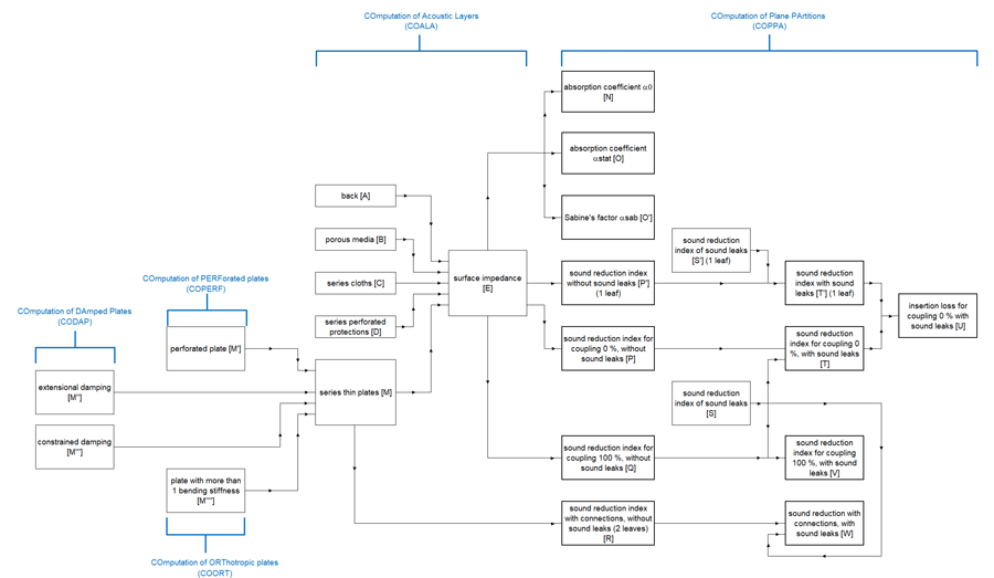
Fig. 1 Computation scheme (block-diagram) for the prediction of acoustic performance of plane partitions and walls with the Module 2 of the software SILDIS®
The routine COALA (COmputation of Acoustic LAyers) is a key computation step of the simulation software SILDIS®, ot what outcome is the surface impedance of the multilayer acoustic structure considered, what is a physical quantity often used on the occasion of simulations relating to sound propagation. For the Module 2 of the software SILDIS®, this routine is accounting (as detailed in the next section) porous media, possibly supplemented by cloths, or/and perforated protections, and also by plates.
In the context of the prediction of acoustic performance of plane partitions and walls, this routine COALA is paired with the routine COPPA (COmputation of Plane PArtitions), involving the derivation of the sound absorption coefficient and of the sound reduction index, which are the ultimate results of the simulation.
The sound absorption coefficient is evaluated on the one hand for normal incidence, and on the other hand (what is obviously a different performance indicator) by the means of an integration between customizable angular limits for sound waves impingement (from what Sabine’s factor is extrapolated).
The sound reduction index is based on integrations between customizable angular limits for sound waves impingement ; sound leaks (i.e. tightness imperfections) can be considered ; coupling between plates sets can be accounted (for a double-leaf partition).
The routine CODAP (COmputation of DAmped Plates) is (as detailed in the next section) a complementary computation step (can be used when needed), allowing the consideration of extensional damping or constrained damping.
The routine COPERF (COmputation of PERForated plates) is (as detailed in the next section) a complementary computation step (can be used when needed).
The routine COORT (COmputation of ORThotropic plates) is (as detailed in the next section) a complementary computation step (can be used when needed), allowing the consideration of plates for which more than 1 bending stiffness is relevant.
A lot of comparisons have been succesfully carried out to check the consistence of results obtained on the one hand with the software SILDIS® and on the other hand by other recognized evaluation means: both for all implemented computations steps considered separately and - of course - globally.
Main and special features, remarkable effects taken into account for the prediction of acoustic performance of plane partitions and walls with Module 2 of software SILDIS®
Regarding acoustics, the main and special features of the software SILDIS® and remarkable effects taken into account in relation to the computation and sizing of plane partitions and walls with the Module 2 can be listed as follows:
- the design is possible for multilayered acoustic structures: most sophisticated combination of materials which can be envisaged (backed either by atmosphere or by an impervious rigid wall) is as shown on figure 2 (thickness of material layers is according to y-axis)
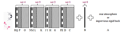
Fig. 2 Multilayered acoustic structure (i.e. combination of materials) considered for the prediction of acoustic performance of plane partitions and walls with the Module 2 of the software SILDIS®® - C, G, K, O : porous medium [3] - D, H, L, P : cloth [4] - E, I, M, Q : perforated protection [5] - F, J, N, R and also B : plate [6]
Thus, acoustic structure basing the acoustic simulation can vary from layer C alone (e.g. in case of a single - naked - melamine foam filling) up to a combination of several soundproofing materials involving porous media, series cloths, series perforated protections and plates depending on the needs (e.g. combination CDE can be used to simulate a mineral wool filling with a cloth and a perforated protection, unless CGK combination is used when all such layers are modelled as porous media [2]) (cf. fig. 2).
For each layer, the input data characterizing its acoustical behavior (porous medium [3] i.e. C, G, K, O or cloth [4] i.e. D, H, L, P or perforated protection [5] i.e. E, I, M, Q or plate [6] i.e. F, J, N, R and also B) the user can:
- either select using materials referenced in dedicated libraries embedded in the software [7]
- or enter directly (BYO [8] concept)
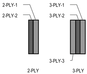
Fig. 3 Geometry of multi-ply plates taken into account with the SILDIS®® software (from left to right): two-component (2-PLY) or three-component (3-PLY)
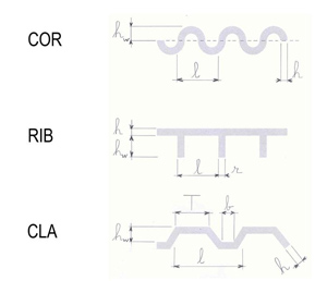
Fig. 4 Geometry of the corrugations of single-component (solid) plates taken into account with the SILDIS®® software (from top to bottom): with sinusoidal undulations (COR), with ribs (RIB) or with trapezoidal profile (CLA)
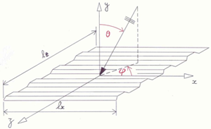
Fig. 5 Geometry of a corrugated plate: coordinates system used for acoustic simulations with software SILDIS®
Depending on the context, marks F, J, N, R and also B in figure 2:
As illustrated in figure 3:
The parameters reflecting the acoustical behaviour of the equivalent plates thus formed are calculated by the SILDIS® software (this is an intermediate evaluation step with a view to predicting the sound reduction index and/or the sound absorption coefficient) from the input data relating to the different components [6] (taking into account the respective thicknesses).
As illustrated in figure 4:For such plates being not perfectly plane, the acoustical behavior is rather complex (referred to as orthotropic), as properties in relation to elasticity differ depending on the axis x or z which is considered (cf. fig 5).
The values of all kinds of stiffness (bending, torsion, in the different directions) are calculated by the SILDIS® software (this is an intermediate evaluation step with a view to predicting the sound reduction index and or the sound absorption coefficient) based on the characteristics of the material considered and taking into account the geometric parameters (as necessary: lx, lz, θ, φ as shown in figure 5 and other dimensions characterizing corrugations), unless the user knows them otherwise, what can then be directly used as input data for performance predictions.
This is not negligible: with the Module 2 of the SILDIS®® software, simulations of the acoustic performance of multiple partitions and walls can be performed by considering for each leaf (shell) one or more juxtaposed plates (then: identical, forming a sub-set), each plate being possibly of any nature among the types mentioned above: mono-material and isotropic, perforated, multi-component, or orthotropic.
Acoustic propagation is taken into account in the different layers, including (if applicable):
- interactions at the interface between porous (in relation to the effective density of the equivalent fluids, and subsequent changes in tortuosity)
- the connections between leaves of a double wall (punctual or linear: with a simplified consideration)
- for an acoustic structure including a porous medium (e.g. polyester, rock wool, basalt wool, glass wool, foam … or which can be air or another fluid): behavior is taken into account on a microscopic scale level in relation with the properties such as flow resistivity (cf. fig. 6) and other parameters parameters for a locally reacting absorber
- the effect of a laminated sound-absorbing filling (each porous layer being with different properties e.g. flow resistivity or other parameters) is taken into account (cf. fig. 7)
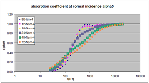
Fig. 6 Sound absorption coefficient at normal incidence - influence of sound-absorbing filling flow resistivity (e.g. when variying from 8kNsm-4 to 72kNsm-4)
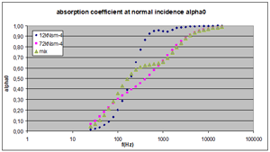
Fig. 7 Sound absorption coefficient at normal incidence - comparison between sound-absorbing filling being monocomponent (e.g. with flow resistivity 12kNsm-4 or 72 kNsm-4) and bicomponent
- the effect of a cloth (e.g. fabric, unwoven) is taken into account, with regard to the resistance to airflow (cf. fig. 8) and also with regard to the vibration (e.g. resonance) of the membrane thus formed (accounting for losses in relation with mounting conditions) (cf. fig. 9)
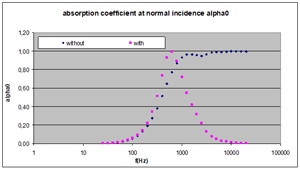
Fig. 8 Sound absorption coefficient at normal incidence - influence of a cloth with regard to the resistance to airflow (with or without)
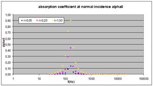
Fig. 9 Sound absorption coefficient at normal incidence - influence of a cloth with regard to membrane resonance
- the effect of a perforated protection (e.g. perforated sheet with circular holes and square or hexagonal array, or with square holes, and also: slotted superficial layer) is taken into account (cf. fig. 10): in terms of sound propagation inside perforations (drillings) and in terms of interaction with a porous medium at the front/at the rear are taken into account ; also for MPP (Micro Perforated Panels)
- the effect of backing (rear atmosphere or impervious rigid back) is taken into account (cf. fig. 11)
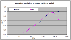
Fig. 10 Sound absorption coefficient at normal incidence - influence of a perforated protection (with or without)
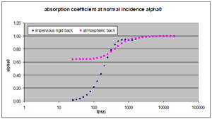
Fig. 11 Sound absorption coefficient at normal incidence - influence of backing
- effect of temperature is taken into account (cf. fig.12)
- effect of pressure is taken into account (cf. fig.13)
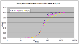
Fig. 12 Sound absorption coefficient at normal incidence - influence of temperature (e.g. 20°C, 300°C, 600°C)
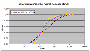
Fig. 13 Sound absorption coefficient at normal incidence - influence of pressure (e.g. 100kPa, 200 kPa, 400 kPa)
Main displayed results (tables and graphs in terms of acoustic performance of plane partitions and walls with Module 2 of software SILDIS®
Main displayed results (tables and graphs) in terms of acoustic performance of plane partitions and walls with Module 2 of software SILDIS® are as follows:
- sound absorption coefficient for normal incidence: α0 i.e. alpha 0 (cf. fig. 14 and 15) per 1/3 octave frequency band and 1/1 octave frequency band for single frequencies as far as the curve is concerned
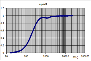
Fig. 14 Sound absorption coefficient at normal incidence - curve
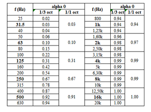
Fig. 15 Sound absorption coefficient at normal incidence - table
- sound absorption coefficient for statistic incidence i.e. between 2 angular limits selected by user: αstat i.e. alpha stat per 1/3 octave frequency band and 1/1 octave frequency band (cf. fig. 16 and 17) for single frequencies as far as the curve is concerned ; practival value α p i.e. alphap is displayed per 1/1 octave band ; weighted sound absorption coefficient αw i.e. alpha w is displayed ; absorption class is displayed
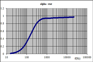
Fig. 16 Sound absorption coefficient for statistic incidence - curve
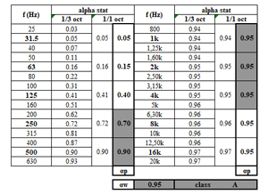
Fig. 17 Sound absorption coefficient for statistic incidence - table
- sound reduction index for statistic incidence i.e. between 2 angular limits selected by user: Rstat per 1/3 octave frequency band and 1/1 octave frequency band (cf. fig. 18 and 19, e.g. in the case of a triple-leaf partitions for which resonnance effects can be observed in low frequency, and for which coïncidence effect can be observed in high frequency) for single frequencies as far as the curve is concerned ; A-weighted overall value with respect to a reference spectrum entered by user, either in 1/3 octave frequency band and 1/1 octave frequency band is displayed ; weighted sound reduction index Rw is displayed ; spectrum adaptation terms C (for pink noise) and Ctr (with predominant low frequencies as in case of road traffic) are displayed
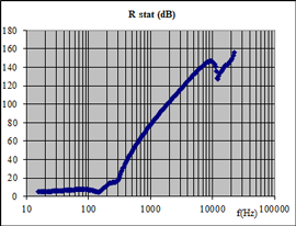
Fig. 18 Sound reduction index for statistic incidence - curve
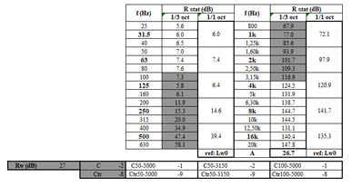
Fig. 19 Sound reduction index for statistic incidence - table
The results of all calculations mentioned above are comparable with the standardized measurement:
- (in case of an atmospheric back) NF EN ISO 140-3 Acoustics - Measurement of sound insulation in buildings and of building elements – Part 3: Laboratory measurement of airborne sound insulation of building elements and ISO 717-1 Acoustics - Rating of sound insulation in buildings and of building elements - Part 1: Airborne sound insulation
- (in case of rigid impervious back) NF EN ISO 354 Acoustics – Measurement of sound absorption in a reverberation room and also ISO 10534-1 Acoustics – Determination of sound absorption coefficient and impedance in impedance tubes – Part 1: Method using standing wave ratio.
- insertion loss for statistic incidence i.e. between 2 angular limits selected by user: ILstat (difference of indicators Rstat relating respectively to overall acoustic structure and basis plate only: e.g. as required to quantity the efficiency of laggings) per 1/3 octave frequency band and 1/1 octave frequency band for single frequencies as far as the curve is concerned ; A-weighted overall value with respect to a reference spectrum entered by user, either in 1/3 octave frequency band and 1/1 octave frequency band is displayed
Complementary displayed results (tables and graphs) in terms of acoustics with Module 2+ of software SILDIS®
With the so-called Module 2+ of the software SILDIS® (which is an extended version of Module 2), complementary displayed results (tables and graphs) for the modeled acoustic structure (with an impervious rigid back), are as follows:
- surface impedance: Z, complex quantity i.e. with a real part and with an imaginary part (cf. fig. 20 and fig. 21), per 1/3 and 1/1 octave frequency band , for single frequencies as far as the curve is concerned ; and also: normalized impedance Z/Z0 (compared to the characteristic impedance F0 of the considered fluid, in the considered thermodynamic context)
- the surface admittance G = 1/Z, complex quantity i.e. with a real part and an imaginary part, in the form of a table which can, after a simple copying and a simple pasting, constitute an input file for calculations with other tools (e.g. based on finite element or boundary element methods) when the latter do not have, for the determination of these quantities, functionalities as powerful as those of the SILDIS® software
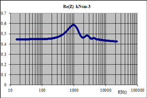
Fig. 20 Surface impedance of a multilayered acoustic structure: real part
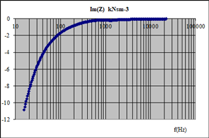
Fig. 21 Surface impedance of a multilayered acoustic structure: real part: imaginary part
The results of the calculations are comparable with the standardized measurement: see ISO 10534-1 Acoustics - Determination of sound absorption coefficient and impedance in impedance tubes - Part 1: Method using standing wave ratio.
What can be added, in relation to the prediction of acoustic performance of plane partitions and walls with Modules 2 / 2+ of software SILDIS®
This user-friendly and multi-purpose calculation mean is useful for the evaluation of acoustical behavior of plane partitions in many contexts (building sector and industry):
- for Research & Development engineers and technicians aiming at developping building elements, in view of the commercialization of optimized and competitive products, for which laboratory measurements and tests would be few in number, as having be, befora nything else, the subject to a selection process after simulations with the sotfware allowing to precise the range of configurations to be explored and subject to a full-size validation
- for acousticians, consultants and architects having to evaluate the performance of construction elements or systems with parameters (materials engineering constants, dimensions) or mounting conditions (e.g. with a temperature gradient) for which no testing reports can be easily obtained
The prediction of acoustic performance of plane partitions and walls with Modules 2 / 2+ of software SILDIS® can be carried out either by the human resources of ITS (which developed and which markets this simulation tool: software publishing is an ITS activity assessed to meet the requirements of standard ISO 9001), or by self-service (with subscription) in ASP [9] mode.
[1] https://www.its-acoustique.fr/images/stories/pdf/report_phrxx-008x.pdf
[2] some cloths and some perforated protections can also be considered as porous layers for the computation
[3] characteristics taken into account: resistivity, porosity, tortuosity, thermal characteristic length, viscous characteristic length, density, thickness
[4] characteristics taken into account: resistance to air flow, mass density, thickness
[5] characteristics taken into account: porosity, geometry of the perforations, mass density, thickness
[6] characteristics taken into account: Young's Modulus, density, Poisson's factor, loss coefficient, installation conditions (free or clamped), dimensions
[7] selected among a software library including for each kind of layer more than 20 referenced materials
[8] BYO = Bring Your Own (anglo-australian acronym)
[9] ASP = Application Service Provider from 250 €/month i.e. 277.50 US $/month ; the fixed price is that indicated in € (the price expressed in US $ is valid, as on December 5, 2019, when 1 € = 1.11 US $) ; VAT with a rate of 20% extra (if applicable, i.e. only for customers established in France) ; commissioning extra