Reducing noise in industrial air networks is an issue with considerable technical and financial stakes, particularly in the case of large cross sections (often rectangular or even square) through which a fluid is transported with a very high flow rate, such as for example in the case of projects including large diameter fans (of the order of 10 m for some cooling towers) or turbomachines (large capacity compressors, combustion turbines even of average power) with regard to both air intake and discharge/exhaust of burnt gases (as the case may be).
It is generally based on the implementation of dissipative silencers, i.e. with a sound-absorbing lining having variable efficiency in a more or less wide frequency band, which, when the implementation of a simple porous lining (with foam, or wool of varying nature) on the periphery of a duct proves not to be appropriate for the acoustic objective, is made of splitters (baffles) between which the fluid circulates, the ratio between their thickness and those of the air passages on the one hand and the length on the other hand impacting all at once (but with antagonistic effects):
- the acoustic performance illustrated by (expressed in dB) sound propagation loss (sound transmission loss) or insertion loss i.e. in relation to the reduction in the sound power level (for the silencer: between upstream and downstream, or between the "with" and "without" configurations)
- the aeraulic (aerodynamic) performance illustrated by (expressed in Pa, daPa, mm of water gauge, or even in millibars depending on individual habits) the total pressure loss i.e. the head loss
The sizing calculations for such equipment, based on Computer Aided Design (CAD) tools, therefore require combined expertise in terms of sound propagation in ducts and in terms of fluid mechanics, for the development of devices constituting the best performance compromise in a given context.
Conventional silencers and silencers with alternate splitter baffles orientation: common aspects and consequences in terms of acoustic and aeraulic (aerodynamic) sizing calculations
Conventional silencers and silencers with alternate splitter baffles orientation have in common the principle underlying their efficiency - dissipation - i.e. (on a microscopic scale) the conversion of acoustic energy into heat by friction on porous structures (sometimes supplemented by a resonant effect linked to the presence of cavities and necks and/or membranes).
Regarding the sound-absorbing elements:
- for conventional silencers (used for decades), they are (cf. figure 1):
- with one of their dimensions equal to that of the duct (rectangular or even square cross-section)
- all parallel to each other (the fluid circulates in parallel galleries)
- for silencers with alternate spilitter baffles orientation (an alternative concept which may prove disruptive?) they are (cf. figure 2):
- with their largest dimension smaller than that of conventional silencer splitter baffles
- with an arrangement (for the same silencer) such that the orientation of the direction corresponding to the largest dimension of the separator baffles is sometimes parallel, sometimes orthogonal (the fluid circulates in a set of galleries forming, as for their frontal section, a grid)
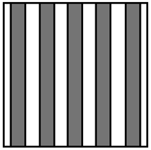
Figure 1 schematic view of a conventional silencer |

Figure 2 schematic view of a silencer with alternate splitter baffles orientation |
Generally speaking, for these two types of dissipative silencers:
- the input data useful for sizing are the same [1]
- the main factors influencing performance are common:
- the service conditions (density and fluid flow velocity)
- the combination of geometric parameters e.g. thickness and spacing of the sound-absorbing lining, length of the silencer
- the properties of the sound-absorbing lining (variable depending on the frequency), often combining porous media[2], surfacing[3] and perforated protections[4] forming sub-assemblies in variable quantities (e.g. from 1 to 4) depending on the assembly considered (cf. Figure 3)
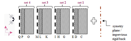
Figure 2 Half-baffle of a silencer with rectangular cross section - Multilayer acoustic structure (i.e. combination of materials) considered for the prediction of acoustic performance of silencers with Module 1 of the SILDIS® software - C, G, K, O: porous medium[2] - D, H, L, P: surfacing[3] - E, I, M, Q: perforated protection[4] |
For the evaluation of acoustic performance - whether for conventional silencers or for silencers with alternate splitter baffles orientation - it is necessary to solve sound propagation equations on the one hand in the airways of the silencer, and on the other hand in its lining to allow the evaluation of the propagation loss Da.L (dB) for a sound attenuator of any length L (m), with the same functional diagram in the case of a locally reacting absorbing material (cf. figure 4).
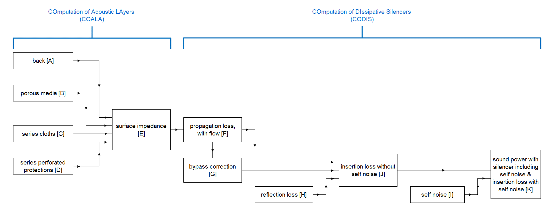
Figure 4 Functional calculation diagram for predicting the acoustic performance of dissipative silencers in the case of a filling made of a sound absorbing material being locally reacting |
Conventional silencers and silencers with alternate splitter baffles orientation: differences in terms of acoustic and aeraulic (aerodynamic) sizing calculations
The calculations, relating on the one hand to conventional silencers and on the other hand to silencers with alternate splitter baffles orientation, differ by the very fact that the simplification constituted by the one-dimensional (1-D) calculation of the acoustic propagation which is based for the former poses a problem for the latter (at the intersections of the grid mentioned above, requiring 3-D i.e. three dimensionnal approach).
As far as conventional silencers are concerned, Module 1 of the SILDIS® software[5][6] developed by ITS human resources as part of its engineering and software publishing activity covered by ISO 9001 certification[7] is dedicated to the prediction of their acoustic and aeraulic (aerodynamic) performance, being the subject of publications illustrating different functionalities[8][9][10][11][12][13][14]:
- with a rectangular or even square cross-section e.g. with baffles or circular with or without a central pod
- for a wide variety of applications (with fluids - not necessarily air - at ambient or high temperatures) both in the building sector (e.g. Heating Ventilation Air Conditioning (HVAC) systems) and in industry, or for environmental protection (ventilation of technical rooms and machine and equipment enclosures for soundproofing, air intake and discharge/exhaust systems for engines and turbomachines)
- regarding acoustics: all the calculation steps in the functional diagram in Figure 4 are programmed, thus allowing the determination of propagation loss (transmission loss), reflection loss, bypass correction, self-noise, an - ultimately - the sound power level downstream of the silencer or "with silencer" and the dynamic insertion loss
- for aeraulics (aerodynamics): the total pressure loss is assessed using proven regressions taking into account the upstream and downstream geometry of the splitters (baffles), as well as their length and roughness
For silencers with alternate spiltter baffles orientation:
- concerning acoustics (to date, without mentioning the methodological improvements currently under development):
- Module 1 of the SILDIS® software mentioned above is used for all calculation steps, with the exception of step [F] of the calculation scheme above; bypass correction and reflection loss are, however, not currently taken into account (in practice: the presence of transverse partitions for the splitters, a sufficiently high open area ratio and a significant silencer length greatly reduce - a fortiori when combined - the imprecision resulting from these simplifications); the self-noise is extrapolated from that of a conventional silencer
- a finite element calculation software (FEM) is used (by the human resource of ITS, which has long invested in such a simulation tool[15] required in the case of silencers with complex geometries for which the calculation based on a 1-D approach - only one dimension considered - as with the SILDIS® software is not appropriate) for step [F] of the calculation scheme above; an important aspect of the methodology is the meshing (cf. Figure 6) and ultimately, the output data are the sound power level downstream of the silencer or "with silencer" and the dynamic insertion loss, resulting from the evaluation of the transmission loss (cf. Figure 7)
- concerning aeraulics (aerodynamics)
- Module 11 of the SILDIS® software mentioned above, created on purpose, allows the evaluation of parameters such as the thickness of the viscous boundary layer, as well as the turbulence kinetic energy (k) and the dissipation rate of the turbulence kinetic energy (ε) required for simulations with the turbulence model (k-ε) - and also a roughness parameter reflecting the presence of perforated protection of the sound-absorbing lining (liner) -
- a computational fluid dynamics (CFD) software is used (by the human resource of ITS, which has long invested in such a simulation tool[15] required in the case of silencers with complex geometries for which the calculation based on regressions as with the SILDIS® software is not appropriate); an important aspect of the methodology is the meshing (similar to the one of figure 6 despite different, given involved physics) and ultimately, the output data is the total pressure loss (cf. figure 8); in addition, spatial distribution of speed vectors can be vizualized with simualtion tool available in ITS (cf. figure 9)
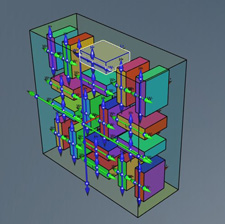
Figure 5 Modeling of a silencer with alternate splitter baffles orientation |
.jpg)
Figure 6 Acoustics - Mesh of a silencer with alternate splitter baffles orientation |
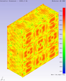
Figure 7 Spatial distribution of sound pressure level basing the determination of the transmission loss of a silencer with alternate splitter baffles orientation |
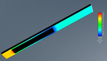
Figure 8 Aeraulics (aerodynamics) - Spatial pressure distribution basing the determination of the total pressure loss for a silencer with alternate splitter baffles orientation (pressure reference is 101325 Pa) |
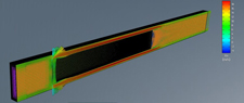
Figure 9 Aeraulics (aerodynamics) - Spatial pressure distribution of speed vectors for a silencer with alternate splitter baffles orientation |
The mesh required for acoustic calculations on the one hand and for aeraulic (aerodynamic) calculations on the other hand are not necessarily the same, if only because the former can often be based on a cell size of the order of half a centimeter (e.g. if one considers 1/8 of the wavelength of the highest frequency of interest and if it is 8 or 10 kHz with a sound speed of 340 m/s) while the latter must take into account - in particular with the turbulence model (k-ε) - the size of the boundary layer in the vicinity of walls (those of the duct, and those that the sound-absorbing lining and splitter baffles extremities - tails, profiled or not - are), the thickness of which - depending on the empty and filled spaces arrangement geometry and on the Reynolds number linked to the kinematic viscosity of the fluid, its speed, and a characteristic dimension - possibly much lower (can be counted in tenths or hundredths of mm in certain cases) and therefore requires much greater sharpness/mesh quality. This of course directly impacts the calculation resources required for simulations, and the calculation times, which, for the former are limited (unless being a manufacturer of aircrafts, rockets or submarines, what ITS is not), and which, for the latter, must remain compatible with the provision of simulation results within timescales compatible with the schedule of industrial projects, often in accelerated mode (fast-tracks).
As far as acoustics is concerned (when sizing a silencer/muffler), taking into account the least attenuated mode (there is more or less a consensus for considering that it corresponds to plane waves) is often, in practice, the approach used when the modal composition of the noise source to be attenuated is not known; in a certain number of cases, the dimensions of the duct section to be considered for the implementation of a noise reduction device are very large, with cross sections that can be counted in tens or hundreds of m2 e.g. intake or exhaust of turbomachines, in particular gas turbines, chimney of Heat Recovery Steam Generator (HRSG), air inlet or outlet of cooling towers with very large diameter fans (which can be close to 10 meters), aircraft engine test benches.
If one uses a finite element method (FEM) calculation software for which the only possibility of considering the least attenuated mode - as far as the sound transmission loss is concerned - is, with a multimodal excitation (equal energy per mode/equal energy density per mode), the limitation of the dimensions of the modeled cross section (to which is linked the cut on/off frequency of the duct which also depends on the Mach number, ratio of the fluid speed to the sound speed for the operating conditions of the silencer), the consideration of the entire cross section of the duct then implies a dependence of the result of the prediction of the acoustic performance on the dimensions of the section considered in a frequency range all the more extended as the corresponding cut on/off frequency is low. This problem also exists in the case of calculations relating to conventional dissipative silencers (with parallel splitter baffles), but the consideration of symmetry planes then facilitates the task which is much more complicated in the case of silencers with splitter baffles with an alternate orientation.
All this contributes in practice to the frequent recourse to computations relating to scale models of silencers with alternate splitter baffles orientation, for which the choice of characteristics is a major issue, with regard to the representativeness of the simulation results.
Conventional silencers and silencers with alternate splitter baffles orientation: comparison of performance in terms of acoustic and aeraulic (aerodynamic) - case study
Performance, relating on the one hand to conventional silencers and on the other hand to silencers with alternate splitter baffles orientation, is multifactorial and has antagonistic effects - therefore: is by nature complex - making comparison tricky beyond specific cases for which the very merits of the comparison can be the subject of legitimate debate, depending on each individual's perspective.
It's a fact: the sizing and development of a silencer is always the result of a trial-and-error approach, aiming to find a compromise namely between dimensions/filling, acoustical performance, and aerodynamic performance, with respect to the objectives of each project.
Thus, in many contexts, the acoustical engineer or technician must consider, for the purpose of comparison, different configurations for which (the list being not exhaustive):
- the frontal section dimensions and/or the length count very much and must be optimized (e.g. if the footprint and/or weight and/or price argument is underlying)
- the quantity of material (for filling the splitter baffles and their frames) must be minimized (e.g. if the weight and/or price argument is underlying)
- some characteristics other than those related to the acoustic performance of materials (for filling the splitter baffles) are critical (e.g. wool without binder in the presence of pure oxygen, wool having to withstand ultra-high temperatures and/or corrosive fluids) (e.g. if the argument of difficulty of supply and/or integration into a production cycle and/or price is underlying)
- a given acoustical performance must be improved or matched with better aerodynamic performance
- a given aerodynamic performance must be improved matched with better acoustical performance
The diversity of these situations contributes to the fact that one does not get bored when working in a design office specializing in acoustics, whether carrying out engineering missions or Research and Development (R&D) work.
Thus, it is possible to compare the performance of a conventional silencer and of a silencer with alternate splitter baffles orientation having the same opening area ratio (which then induces a lesser thickness for the splitter baffles of the conventional silencer).
Or it is also possible to compare - as done hereafter, in the context of a case study - the acoustic and aerodynamic performance of two silencers, each based on one of the concepts (conventinal or with alternate splitter baffles orientation) that differentiate them, by considering:
- for the splitter baffles: the same lining, the same thickness (2d), and the same length (L) in the direction of gas flow
- for the air passages: the same spacing, i.e. the same distance - assumed to be unique, what is not mandatory in general - between parallel sound absorbing surfaces (2h) / sound absorbing surfaces and duct walls (h), and the same Mach number M (ratio of the fluid flow velocity to the speed of sound under operating conditions)
For example, one can set d/h=2, L= 1m and M≈0 (this is valid even with a non-zero flow when a sufficiently high sound speed is used for simulation) to avoid to consider the influence on sound transmission loss of gas speed which is - when comparing conventional arrangement and splitter baffles with alternate orientation - different in airways if equal at silencer entrance, and vice versa.
The other variables used for the simulation of acoustical performance are not detailed here, knowing that when using finite element method (FEM) calculation software for which the only possibility of considering the least attenuated mode is the limitation of the dimensions of the modelled cross section, the input data that must be taken into account to enable the display of output data such as the (sound) transmission loss in a wide frequency range do not necessarily correspond to ordinary practical applications. This is the case of the simulation presented here, and the following observations are therefore not intended to be generalised identically with certainty to all concrete situations for which the parameters (both geometrical, and those relating to the properties of the sound-absorbing lining and the service conditions) may be very different from those used for simulation; this does not mean, however, that the trends observed here are not reproducible in other circumstances (a case-by-case study is recommended to assess the accurate extent of the benefits of using silencers with alternating-orientation splitter baffles, although other observations support the trend provided by the presented case study for what concerns acoustical performance for low and mid frequencies).
As far as aeraulic (aerodynamic) performance is concerned, this case study is based on rectangular ends upstream and downstream of the sound-absorbing lining and on a front velocity of 20 m/s (at silencer entrance, along longitudinal axis); "smooth" behavior is assumed.
What emerges from the case study is that the silencer with alternating-orientation baffle dividers has:
- acoustic performance - in the frequency band studied - similar to that of the conventional silencer, except for the frequency range corresponding to maximum performance (in practice, this is sometimes unnecessarily high, often impaired by surfacing or perforated protection, or diminished by flow noise, i.e. silencer's self noise)
- aeraulic performance that clearly favors them (the pressure drop is apprximately reduced by half)
Regarding acoustics, sound transmission loss is displayed below (cf. Figure 10):
The acoustic performance of a dissipative silencer (i.e. whose principle is based on the presence of sound-absorbing materials) is generally not very intuitive - due to the multiplicity of factors of varying importance and having more or less antagonistic effects and due to the complexity of the phenomena involved -, and, unlike a conventional silencer, for which the dimensionless parameter r[16] based on resistivity, thickness and characteristic impedance is unique, it is necessary to consider two mutually perpendicular directions in the case of silencers with alternate splitter baffles orientation, which may appear dissuasive with regard to simplistic attempts at explaining the causes underlying the results of the comparison between the configurations considered; a complete theory that would encompass all the cases of figures is currently lacking - in relation to what the possibility of carrying out case-by-case performance simulations is very helpful.
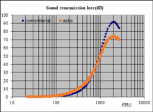
Figure 10 Comparative transmission loss of a conventional silencer and of a silencer with alternate splitter baffles orientation (asbo) |
Regarding aeraulics (aerodynamics), total pressure loss is displayed below (cf. Figure 11):
ΔP = ξ * (1/2 * ρ * Vp2)
with:
ΔP : total pressure loss (Pa)
ξ : coefficient linked to the geoometry of splitter baffles arrangement
ρ : fluid density (kg/m3)
Vp : fluid passage speed (in airways) (m/s)
For a given face velocity Vf, the passage velocity (in the airways) Vp is, compared to that of a conventional silencer, lower in the case of a silencer with alternate splitter baffles orientation (because the opening area ratio OAR is higher, which can also - all other things being equal - have a favourable influence on ξ - no regression linking ξ to OAR is available in specialized literature in the case of obstacles having the geometry of alterne splitter baffles orientation: Computational Fluid Dynamics - CFD - evaluation is required here).
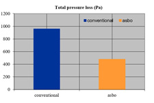
Figure 11 Aeraulics (Aerodynamics) - Comparative total pressure loss of a conventional silencer and of a silencer with alternate splitter baffles orientation (asbo) |
It is open to consider that a corollary to the situation reported above is that, for equivalent total pressure loss, the acoustic performance of a silencer with alternating orientation separator baffles can be be superior to that of conventional silencers; the frequency band of interest matters for this kind of comparisons.
It should be noted that such observations, if transposed to practical cases of noise reduction of turbulent gas flows (a fortiori very turbulent) opens the field of possibilities for soundproofing turbomachines in particular (for a combustion turbine for example, the speed of the gases at the connection flange upstream of the exhaust line is measured in hundreds of kilometers per hour - and they are swirling -, the total pressure loss is a major issue in the sizing of silencers, and the fact that the latter can at the same time linearize the gas flow is a very appreciable aspect).
Conventional silencers and silencers with alternate splitter baffles orientation: overall
ITS can perform acoustic and aeraulic (aerodynamic) sizing computations for silencers with alternate splitter baffles orientation, to quantify performance and optimize it in all contexts.
Regarding enginneering and consulting, ITS's field of intervention includes not only simulations with tools using the Finite Element Method (FEM) and Computational Fluid Dynamics (CFD) but also assistance in the choice of materials for sound-absorbing elements filling and the development of construction systems (depending on the context of each project).
Soundproofing systems based on this concept offer good performance, both in terms of sound power level reduction (which varies with frequency, but which is generally sufficiently high) and total pressure loss (generally sufficiently moderate), offering in many cases a very good (if not better e.g. when the total pressure loss is significantly reduced, with similar sound attenuation in a wide frequency range) compromise between noise reduction and pressure drop (which are inseparable when assessing the quality of a silencer).
The filling of the alternating orientation splitter baffles is not necessarily limited to a porous medium (e.g. mineral wool, glass wool) with surfacing (e.g. fabric) and perforated protection (sheet metal with holes) constituting a single acoustic structure, but it can include alternate i.e. dissimilar (unsymmetrical) sound-absorbing linings or be (partly) reactive e.g. acting as a resonator i.e. with an efficiency based on the presence of a membrane or a resonant volume and a neck, according to techniques used for the improvement of the acoustic performance of conventional silencers, particularly at low frequencies[17][18][19]; this increases the possibilities of silencer designs adapted to all contexts, with a performance adjusted to more or less specific objectives (depending on the desired attenuation level, and the frequency range of interest), and always with a reduced pressure drop.
Furthermore, since the splitter baffles have a transverse dimension smaller than the dimensions of the duct cross-section, dimensional variations induced by sudden temperature changes (related to expansion) do not cause the fragility observed (sometimes with adverse consequences for the longevity of the structures) in case of conventional silencers, for which the interface between the elements constituting the sound-absorbing lining and the silencer casing often poses problems due to unsustainable thermal constraints.
For aeraulic networks transporting high-temperature fluids, a field of application for silencers with alternate splitter baffles orientation is therefore - among others - the field of flue gas exhaust systems as required for gas turbines whose operation, especially when split over time intervals - e.g. to balance electricity supply and demand, or if it comes to emergency facilities - puts severe strain on the elements of a silencer, as well as the chimneys (stacks) of Heat Recovery Steam Generators (HRSG) and test benches exhaust lines (e.g. for jet aircraft engines).
This alternative (disruptive?) technology can also be used at much lower operating temperatures, particularly at ambient temperature, e.g. for air intakes of gas turbines, industrial compressors and (a fortiori when the frontal section is large and/or when the volume flow is high and/or when the acoustic and aerodynamic performance objectives are ambitious) for the suction and discharge of various industrial processes involving or not the use of fans with large diameters (e.g. test rooms, technical premises, air condensers).
The selection of the components of the sound absorbing filling of the silencers with alternate splitter baffles orientation, and the combination of geometric parameters (baffle thickness, spacing, length) conditions - for given service conditions - the acoustic performance of such noise attenuators, and a compromise must, for each application, be found on a case-by-case basis with the aerodynamic performance (without forgetting the influence of the self-noise due to flow), according to the more or less specific objectives of each project: this is the very heart of ITS's know-how.
Furthermore, the fabrication (in Europe or on other continents) of silencers with alternate splitter baffles orientation based on sizing and specifications of ITS (as regards acoustics and aeraulics/aerodynamics) can be carried out by a partner company of ITS - which can therefore also be called upon for the supply of such soundproofing materials -, for an optimized consideration of other technical imperatives (e.g. mechanical stability and resistance to stress linked to temperature variations of structures and sub-assemblies, interfacing and integration with other constructions, compliance with specific sizing and construction rules, e.g. domestic), for the sourcing of first-choice raw materials, for the implementation of the best shaping and assembly techniques at controlled costs and for a smooth project management in compliance with agreed deadlines; it is a matter of quality constructions combining competitiveness, performance and durability, capable of satisfying the most demanding customers in this area e.g. in the energy production sector and elsewhere.
Spread the word !
[1] cf. What are the input data useful for the design of a silencer ?
[2] properties: resistivity, porosity, tortuosity, thermal characteristic length, viscous characteristic length, density, thickness
[3] properties: airflow resistance, mass density, thickness
[4] properties: porosity, perforation geometry, mass density, thickness
[5] cf. Prediction of acoustic and aerodynamic performance of silencers - software SILDIS® Module 1
[6] Sound Impact Limitation Design for Industrial Solutions cf. https://www.its-acoustique.fr/en/acoustical-insulation-soundproofing/acoustic-aeraulic-construction-cad-calculation-software.html
[7] cf. Quality management
[12] cf. Design and calculations of high performance baffle (splitter) silencers
[15] cf. https://www.its-acoustique.fr/en/updates/acoustic-aerodynamic-finite-element-modeling-silencer
[16] r = σ * d / Z0 with σ flow-resistivity of unique porous medium (Nsm-4), d half-thickness of porous medium (m), Z0 charactéristic impedance of fluid (gas) (Nsm-3)