Resonators are devices based on different construction systems designed for sound absorption/attenuation for a variety of applications in the field of acoustic insulation, in both the building and industrial sectors:
- sound absorbing linings for acoustic treatment of premises (i.e. to reduce sound reverberation, e.g. living spaces, speech and listening rooms, test benches and acoustic measurement rooms)
- silencers liners (to limit the transmission of noise from aeraulic ducts e.g. air intake and exhaust of burnt gases from combustion turbines or pressurized fluid networks)
Their use is namely envisaged in various circumstances:
- when strong sound absorption/attenuation is required within a specific limited frequency range (e.g., for a silencer in a ventilation system, when a fan emits a spectral line, i.e., when its acoustic power is concentrated within a limited frequency range - this can also apply to an internal combustion engine at exhaust -); sometimes also when seeking to enhance the effectiveness of a dissipative soundproofing device
- when one desires to avoid the drawbacks sometimes associated with the use of fibrous materials for soundproofing (wool of all kinds) or of acoustic foams (e.g. when their presence would result in prohibitive weight, when a hostile environment - high temperature, aggressive physicochemical composition of a fluid with which they would be in contact, risk of erosion due to the speed of a gas flow, effects of humidity - would be likely to alter their acoustic behavior - sometimes poorly known due to the difficulties in precisely characterizing it in the laboratory, beyond samples that are not always representative of production with variations over time, not to mention changes in composition sometimes induced by evolving health standards - and/or to degrade them in the short or long term, with possibly undesirable contamination due to released particles); such fillings are not eternal in any case, even in more or less ordinary atmospheres.
Resonators have long been a field of investigations and attempts for innovation for acousticians; they presently cover a wide variety of constructions, each associated with high acoustic performance over a more or less narrow frequency range (around a principal resonance frequency from which they derive their name), generally less wide than that of dissipative devices (the latter being essentially related to the presence of porous materials, whose efficiency is usually broadband, without a peak in frequency performance), involving coupling:
- between cavity(ies) and membrane(s) i.e. using plate(s)
- between cavity(ies) and neck(s): then referred to as Helmholtz resonator(s) in homage to a very great 19th-century physicist
Module 1 - prediction of the acoustic and aerodynamic performance of silencers - and Module 2 - prediction of the acoustic performance of plane (flat) partitions - of the software SILDIS® allow to consider, for the modeling of resonators, an acoustic structure such as that of figure 1, combining up to 4 sets made up - each - of a porous medium with possibly a surfacing or even a perforated protection.
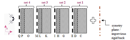
Figure 1 Multilayered acoustic structure (i.e. combination of materials) considered for predicting the acoustic performance of resonators with the software SILDIS® - C, G, K, O: porous medium - D, H, L, P: surfacing (possibly: plate) - E, I, M, Q: perforated protection |
For sound absorption/attenuation, the CAD software SILDIS® allows the modeling of hybrid resonators combining cavities, membranes & perforations (separately or together).
Modeling of plate resonators - coupled cavity(ies) and membrane(s) for sound absorption/attenuation using CAD software SILDIS®
Modeling resonators with coupled cavity(ies) and membrane(s) for sound absorption/attenuation has long been possible with the CAD software SILDIS®, as illustrated by various publications presented on other pages of this website, from which the figures below are extracted (often, the performance of such resonators is maximized at low and medium frequencies):
- Acoustics - Boosting silencer performance with software SILDIS®[1] cf. fig. 2-3 below
- Design and calculations of high performance baffle (splitter) silencers[2] cf. fig. 2-3 below
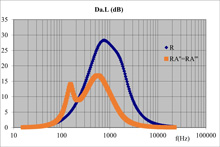
Figure 2 Comparative propagation loss of baffle silencers with single or alternating packing (with a membrane resonator): influence of construction |
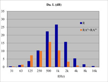
Figure 3 Comparative propagation loss (per octave band) of baffle silencers with single or alternating packing (with a membrane resonator): influence of construction |
- Acoustics – Design and sizing of plate resonators with circular, square or slotted perforations or not perforated (for silencers and absorbing linings) with software SILDIS®[3];cf. fig. 4-5 below
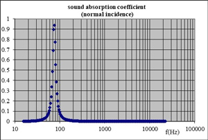
Figure 4 Sound absorption coefficient (for normal incidence) of a resonator consisting of a 0.06 m thick layer of foam with a flow resistivity of 10.5 kN/m⁻⁴ and a porosity of 0.95, covered with a non-perforated plate with a surface mass of 7.8 kg/m², without taking into account the plate's rigidity. At a frequency of 76 Hz, the sound absorption coefficient for normal incidence reaches 0.94. |
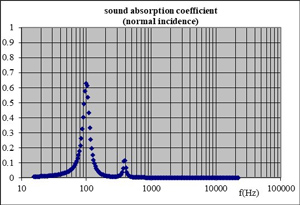
Figure 5 Sound absorption coefficient (for at normal incidence) of a resonator consisting of a 0.06 m thick layer of foam with a flow resistivity of 10.5 kNsm⁻⁴ and a porosity of 0.95, covered with a non-perforated plate with a surface mass of 7.8 kg/m², taking into account its rigidity (steel plate, 0.25 m x 0.25 m, simply supported edges). At a frequency of 99 Hz, the sound absorption coefficient for normal incidence reaches 0.63. |
The figures above illustrate different possibilities for sizing plate resonators, taking into account the following properties (for each layer of the acoustic structure in Figure 1):
- porous materials, modeling cavities (when not air): airflow resistivity, porosity, tortuosity, thermal characteristic length, viscous characteristic length, density, thickness
- surfacings: resistance to air flow, mass density, thickness; and when it comes to plates whose flexibility is considered: Young's modulus i.e. elastic modulus, density, Poisson's ratio, loss coefficient, dimensions, installation conditions (e.g. "free/supported" or "clamped") for an appropriate simulation of the vribroacoustic behaviour
Modeling of Helmholtz resonators - coupled cavity(ies) and neck(s) / perforations for sound absorption/attenuation using CAD software SILDIS®
The modeling of Helmholtz resonators, i.e. devices with coupled cavity(ies) and neck(s) / perforations for sound absorption/attenuation, has long been possible with the SILDIS® CAD software, as illustrated by various publications presented on other pages of this website, from which the figures below are extracted (in general, the performance of such resonators is maximum for medium-high frequencies):
- Acoustical sizing calculations for panels with millimetric or sub-millimetric perforations for soundproofing[4];cf. fig. 6-7 below
|
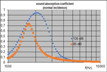
Figure 6 illustration of the non-linearity of the response of a micro-perforated plate to a sound excitation: sound absorption coefficient for normal incidence (with a ratio of the diameter of the circular perforations to the thickness of the plate of 1, a porosity of 2%, a cavity depth of 0.01 m, sinusoidal swept sound source with a level of 85 dB or 135 dB (taking into account reflections on the sound-absorbing lining) |
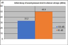
Figure 7 illustratation of the non-linearity of the response of a micro-perforated plate to sound excitation: initial decay of the sound pressure level (dB/m) for a dissipative silencer consisting of 0.1 m air channels and the micro-perforated plates described in Figure 6, under the service conditions of Figure 6 (propagation loss per unit length valid at the silencer inlet); the resonance frequency of the sound-absorbing lining (for the 1/1 octave band centered on 2 kHz) is considered |
- Modeling of dissipative silencers - refinement of the calculation of acoustic performance - SILDIS® software[5];cf. fig. 8 below
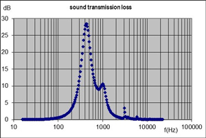
Figure 8 Transmission loss of a rectangular cross-section silencer as simulated with Module 1 of the SILDIS® software. This is a double resonator consisting (from back to front) of an air gap 0.05 m thick with a circularly perforated plate of diameter 0.0003 m (perforation rate 1%), an air gap 0.06 m thick with a circularly perforated plate of diameter 0.0003 m (perforation rate 1.77%), with a transmission rate of 33.3%, a length of 1.2 m. At ambient temperature, with zero fluid velocity, the transmission loss reaches 10.6 dB (i.e. 8.8 dB/m) for the frequency 1 kHz. |
- Acoustics – Design and sizing of plate resonators with circular, square or slotted perforations or not perforated (for silencers and absorbing linings) with software SILDIS®[3] cf. fig. 9-13 below
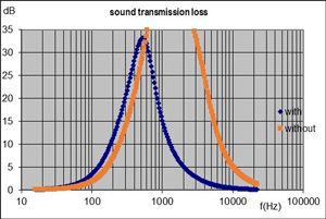
Figure 9 Transmission loss of a resonator silencer with a 50% transmission rate, 1.2 m long, made of 0.12 m thick baffles of 10.5 kNsm-4 air flow resistivity foam, 0.95 porosity, with or without a perforated plate with 0.01 m wide slots (perforation rate 10%). For frequency 250 Hz, the transmission loss reaches 16.0 dB (i.e., 12.8 dB/m) with the perforated protection, compared to 10.3 dB (i.e., 8.2 dB/m) without the perforated protection, which allows (if performance at 250 Hz is the primary concern) a reduction of more than one-third in the silencer length. |
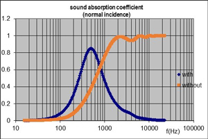
Figure 10 Sound absorption coefficient (for normal incidence) of a resonator made of 0.04 m thick foam with an airflow resistivity of 10.5 kNsm-4 and a porosity of 0.95, with or without a perforated plate with slots 0.001 m wide (perforation rate 2%). At a frequency of 500 Hz, the sound absorption coefficient for normal incidence reaches 0.85 with the perforated plate, compared to 0.38 without the perforated plate. |
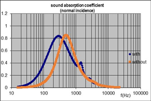
Figure 11 Sound absorption coefficient (for normal incidence) of a resonator made of 0.04 m thick foam with an airflow resistivity of 10.5 kNsm-4 and a porosity of 0.95, with or without a perforated plate with slots 0.001 m wide (perforation rate 2%). At a frequency of 250 Hz, the sound absorption coefficient for normal incidence reaches 0.83 with a rear air gap (plenum) of 0.08 m, compared to 0.46 without a rear air gap (plenum). |
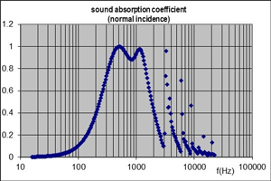
Figure 12 Sound absorption coefficient (for normal incidence) of a double resonator consisting (from back to front) of an air gap 0.05 m thick with a plate of circular perforations of diameter 0.0003 m (perforation rate 1%), and an air gap 0.06 m thick with a plate of circular perforations of diameter 0.0003 m (perforation rate 1.77%). For the frequency 1 kHz, the sound absorption coefficient for normal incidence reaches 0.94. |
Figure 13 Transmission loss of a resonator silencer with a transmission rate of 33.3%, a length of 1.2 m consisting of splitters (baffles) made up of two layers as described in the legend of Figure 12, installed back to back (an infinitely rigid impermeable partition could be required between them, as well as transverse partitions?). For the frequency 1 kHz, the transmission loss reaches 10.6 dB (i.e. 8.8 dB/m). |
The figures above illustrate different possibilities for dimensioning Helmholtz resonators - based on the coupling of cavity(s)/perforation(s) -, taking into account the following properties (for each layer of the acoustic structure in Figure 1):
- porous materials, modeling cavities (when not air): airflow resistivity, porosity, tortuosity, thermal characteristic length, viscous characteristic length, density, thickness
- perforated protective materials: porosity, perforation geometry[6], mass density, thickness (possibly micro-perforated plates - MPPs - i.e. with sub-millimetric perforations or with larger drillings)
Modeling of hybrid resonators – cavities, membrane(s) and perforation(s) coupled for sound absorption/attenuation – using CAD software SILDIS®
For sound absorption/attenuation, the CAD software SILDIS® allows the modeling of hybrid resonators combining cavities (at least 2), membranes (diaphragms) & perforations with great design freedom, in a context where obtaining sufficiently good acoustic performance (as the case may be: sound absorption of a lining or attenuation of a silencer) in a sufficiently wide frequency band (as is required in practice in many cases) is no small matter.
Actually, it is possible to develop soundproofing devices comprising up to 4 resonators mounted in series i.e. with up to 4 sub-sets as in Figure 14 and/or Figure 15 stacked to make the total thickness of the sound-absorbing lining (the non-perforated plate in Figure 15 is not necessarily a single piece, but can be made up of the juxtaposition (not schematized) of rectangular or circular - each being possibly a small flexible panel - non-perforated elements forming a mesh - developments are in progress -).
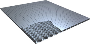
Figure 14 Micro-perforated plate forming the surface layer of a honeycomb sandwich panel (combination of elements QO, MK, IG, EC of Figure 1) |
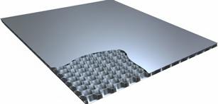
Figure 15 Non-perforated plate forming the surface layer of a honeycomb sandwich panel (combination of elements PO, LK, HG, DC of figure 1) |
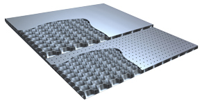
In the current state of software development, all cavities in a given set (as illustrated in Figure 1) have identical dimensions; cavities of a given set can have dimensions being different from cavities of another set, both in terms of depth and other dimension (if cylindrical cells are considered) or in terms of all other dimensions (if a different geometry is considered); viscous and thermal effects are taken into account to model sound propagation (within the cavities, in relation to boundary layer effects). The interface between two cavities can be made of a perforated or non-perforated plate (as a choice, with the possibility of mixing them: these are then hybrid resonators). As an example, Figure 16 illustrates the case of a hybrid resonator, combining 2 cavities, a perforated plate and a non-perforated plate; either of the plates can be at the front - and then the other at the rear - however with a more or less different acoustic performance (depending on the frequency) for each assembly (the resonator is not tuned in the same way).
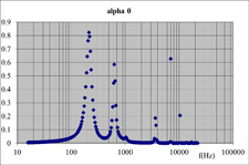
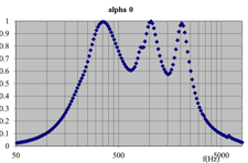
Figure 17 illustrates the sound absorption coefficient for normal incidence of a hybrid resonator modeled with the CAD software SILDIS®, combining two cavities, a perforated plate (1 mm thick) and a non-perforated plate (1 mm thick), the total thickness of the sound-absorbing lining being 102 mm. As in the case of the double Helmholtz resonator, illustrated in Figure 12, two distinct resonance frequencies are associated with it; depending on the intended effect, it may be desirable for them to be closer together, to enhance the effectiveness of the device at a single frequency - or in the vicinity of a single frequency, by increasing the frequency range in which the device is effective (i.e. by increasing the bandwidth of the acoustic filter that the resonator is) - or further apart, e.g. to obtain the effectiveness of the device with respect to two spectral lines that would be emitted by a given noise source.
|
Figure 16 Hybrid resonator combining 2 cavities, a perforated plate, and a non-perforated plate for sound absorption/attenuation |
Figure 17 Sound absorption coefficient for normal incidence of a hybrid resonator, combining 2 cavities, a perforated plate and a non-perforated plate |
The calculation of the performance of hybrid resonators, by an analytical method, with the SILDIS® software is carried out by combining the best of the specific functionalities developed to model on the one hand membrane resonators and on the other hand Helmholtz resonators (with perforations); for each of the components of hybrid resonators, the input data taken into account for the dimensioning are all those mentioned above. It is even possible to consider, for some "sets" (or indeed: for all), special plates combining the properties linked on the one hand to a surfacing (depending on the context: either mass density and resistance to air flow, or Young's modulus i.e. elastic modulus, density, Poisson's ratio, loss factor, dimensions and installation conditions - e.g. "free/supported" or "clamped" -) and on the other hand the properties linked to perforations (geometry, dimensions).
Figure 18 illustrates the normal incidence sound absorption coefficient of a hybrid multilayer resonator modeled with the CAD software SILDIS®. This resonator consists of 3 cavities and 3 special membranes combining the properties of perforated plates (1 mm thick) and of flexible plates (considering the material elastic i.e. flexural characteristics and boundary conditions). The total thickness of the sound-absorbing lining is 102 mm. The combination of the plate dimensions (thickness, perforation diameter, open area ratio) and of cavities depths - given the flexural behavior of the membranes - allows for the development of a device capable of broadband sound absorption, as the simulated sound absorption coefficient for normal incidence is at least 60% for ten adjacent 1/3-octave frequency bands; the acoustical properties of such an hybrid resonator are therefore very different from those relating to the (also hybrid) resonator of which performance are illustrated in figure 17, despite considered plates thickness and overall depth are the same.
|
Figure 18 (Broadband) Sound absorption coefficient of a multilayered resonator (for normal incidence) |
|
As with the other calculations carried out with Module 1 - prediction of the acoustic and aerodynamic performance of silencers - and Module 2 - prediction of the acoustic performance of plane (flat) partitions - of the software SILDIS®, the service conditions (nature of the fluid, pressure, temperature - and in the case of silencers: gas flow velocity) are considered, and the frequency range accounted is at least 20 Hz - 20 kHz (taking into account human hearing sensitivity), to allow for various industrial applications.
In the particular case of liners (sound-absorbing linings making silencers infills, particularly for turbomachinery e.g. aircraft engines, combustion turbines at both intake and exhaust), when the superficial layer (in contact with the transported fluid) of a hybrid resonator is a perforated plate (as in the case of Helmholtz resonators mentioned above, but this is not mandatory) of which elastic cosntants can be considered, the influence of the Mach number (on the acoustic impedance and therefore on the absorption coefficient and propagation/insertion loss in the case of an absorber locally reacting) is taken into account, as is the impact of high noise levels (in nonlinear regimes), which plays a significant role in the performance of microperforated panels (MPPs) for which modeling thermal and viscous effects (as is the case with the SILDIS® software) is essential. For silencers with splitter baffles, hybrid resonators - combining cavities (at least 2), perforated and non-perforated plate(s) - can make a lining that can be simulated with the SILDIS® software when the sound-absorbing elements are all parallel to each other, with a (single) height equal to one of the transverse dimensions of a rectangular duct and can be considered as being locally reacting (this is not the case for separating baffles with an alternate orientation).
Selecting in the best possible way (with the consideration of all contextual elements) the operating principle of a resonator, defining its multilayered structure and adjusting its dimensional parameters to a given performance objective, considering the entire frequency range - sometimes very wide - in which efficiency is sought is often a challenge, due to the complexity of the phenomena involved and the antagonistic impact of different parameters (not to mention the constraints of compactness, the rise in the thickness of the sound-absorbing lining to increase acoustic performance at low frequencies, linked to the depth of the cavities, often causing problems): having available technologies based on complementary efficiency principles such as those linked on the one hand to a coupling cavity(ies)/membrane(s) and on the other hand to a coupling cavity(ies)/perforation(s), to which are associated performances adjustable according to frequency - and which can be simulated with a reliable tool - is an advantage.
Hybrid resonators combining cavities (at least 2), membrane(s) i.e. flexible plate(s) and perforated plate(s), which can be sized - for all aspects realting to acoustics - with the CAD software SILDIS®, increase the possibilities of developing sound absorption and/or noise reduction devices that are both effective and durable (most of the time: entirely metallic, without porous materials) for diverse uses for which further improvements & validations are underway.
Spread the word !
[1] Acoustics - Boosting silencer performance with SILDIS® software
[2] Design and calculations of high performance baffle (splitter) silencers
[6] Possible geometries for modeling resonator perforations
   
geometry of plates with perforations (in order of display) circular (orthogonal or hexagonal arrangement), square or slotted, taken into account with the software SILDIS® |