The SILDIS®[0][1] software (in Excel format) enables the simulation of the sound reduction of materials/partitions, as illustrated by an example (numbered 2.4.0.0 in the user's manual), which is one of the simplest possible cases, as it involves a single layer (a porous medium, specifically foam), whereas Module 2 of the software also allows for calculations regarding non-monolithic structures (i.e. those with multiple layers of potentially different types), which may involve (in addition to porous media, the latter being also possibly mineral wools made of rock, basalt, glass, polyester or ceramic fibers):
- surfacing layers: e.g. glass veils, needle-punched mats, fabrics; in certain software versions, these can be assigned the properties of thin elastic plates
- perforated protective layers: e.g., perforated plates
- thin plates: e.g. sheet metal, glazing, masonry elements, plasterboard, wood panels
In total, up to 17 layers of such materials can be combined to model an acoustic structure for which one wishes to simulate the performance regarding limitation of sound transmission through it aka sound transmission loss, as illustrated by the metric commonly referred to as the sound reduction index.
Problem statement for simulating the sound reduction of a material/partition using SILDIS® software (example)
The objective is to simulate the sound reduction of an acoustic structure consisting entirely of a single layer [1] of melamine foam [2] using the general JKD porous medium model [3] with a thickness of 0.1 m [4], considering air at 20 °C [5] and a pressure of 101325 Pa [6], an infinite wall surface [7] and an integration of the sound transmission factor between 0 and 89.375° (statistical incidence i.e. random) [8]. The language used is English [9].
The evaluations therefore concern an acoustic structure identical to that of another calculation example using the software - processed separately[2] - though with the following differences in this case:
- a different parameter regarding the acoustic structure (a "rear atmosphere" i.e. air instead of an impervious rigid back aka an impermeable rigid backing; the user need only modify a single Excel cell in the program to account for this)
- a different performance indicator (sound reduction index instead of sound absorption coefficient); this has no impact on the tasks required of the user, since the results of both calculations are displayed - simultaneously - on the same Excel sheet, provided the user chooses to view the results of the other separately processed example[2] on the "in-out COPPA" sheet, just as they must do to view the results of the current calculation; for that other separately processed example[2] - and for that one alone - the results are - additionally - displayed on a separate Excel sheet ("in-out COPPA0")
Input data to be entered for simulating the sound reduction of a material/partition using SILDIS® software (example)
The input data to be entered into the "in-COALA" Excel sheet of Module 2 of the SILDIS® software, for the simulation of the sound attenuation of the soundproofing material used as an example, are (with one exception) the same as those listed for the separate calculation example discussed elsewhere[2]. The exception concerns the entry for the question "Rear atmosphere? (0/1)" (where 1 indicates "yes" and 0 indicates "no"); in this case, the value 1 (instead of 0) must be entered in cell O7. The complete set of input data is listed below so that this article can be read independently of the one covering the separate calculation example[2].
The line concerning the sole modification of the input data considered for the other calculation example using the software which is treated separately[2] is in italics.
The input data required for the calculation are listed below, referencing the information provided above (see the bracketed numbers in the previous section, used as markers to explain the selection below). Input cells are identified by their Excel coordinates (column/row) in the following excerpt from the user manual.
Input data to be entered in the "in COALA" Excel worksheet for visualizing results in the "in-out COPPA" Excel worksheet
| Item | Cell for input | Foreseen action | Input | Landmark / comment |
| Language | AF2 | For English, select E,; for French, select F | F | [8] |
| Temperature (°C) | D5 | Enter a real number | 20 | [5] |
| Pressure (Pa) | D6 | Enter a positive real number | 101325 | [6] |
| Rear atmosphere ? (0/1) | O7 | For "yes", enter 1; for "no", enter 0 | 1 | [7] |
| Maximum set index imax | D19 | Entrer un nombre réel positif | 1 | [1] |
| Reference | J21 | Select a model (in a drop-down menu) | MELAMINE | [2] |
| General model for porous medium | J27 | Select a model (in a drop-down menu) | JKD | [3] |
| Thickness (m) | J56 | Enter a positive real number | 0.1 | [4] |
| Incorporation of the series cloths | AB26 | For "yes", enter 1; for "no", enter 0 | 0 | [1] |
| Incorporation of the series perforated protections | J125 | For "yes", enter 1; for "no", enter 0 | 0 | [1] |
| Number of identical plates | AB68, AC68 | Entrer un nombre réel positif | 0 | [1] |
Remarks:
- since the material considered for the porous medium in the example is one of those with properties listed in a library (specifically material list no. 3, which must be selected in cell D21 for it to appear in the material reference drop-down menu), the user does not need to enter the properties manually (in cells M22 respectively N22 onwards) by selecting for cell J21, in the material reference drop-down menu: BYOb respectively BYOa (BYO = Bring Your Own)
- since the selected general porous material model is not CUM - nor KIR for "internal use" (i.e. when the software is used at ITS) -, the user does not need to enter a regression coefficient sub-model (CUM/KIR general model) in cell Q31 by selecting CUM - or KIR for "internal use" (i.e. when the software is used at ITS) - in the general porous media model drop-down menu (cell J27)
Input data to be entered in the "in COPPA" Excel Worksheet
| Item | Cell for input | Foreseen action | Input | Landmark / comment |
| Orientation fi min i.e. φmin | AF2 | Select a model (in a drop-down menu) | 5.625 | for "external use": φmin = 5.625° (this choice is inconsequential for an isotropic partition, mattering only in the case of an orthotropic partition) [1] |
| Orientation fi max i.e. φmax | D5 | Select a model (in a drop-down menu) | 84.375 | for "external use": φmax = 84.375° (this choice is inconsequential for an isotropic partition, mattering only in the case of an orthotropic partition) [1] |
| Incidence teta min i.e. θmin | D6 | Select a model (in a drop-down menu) | 0 | [8] |
| Incidence teta max i.e. θmax | O7 | Select a model (in a drop-down menu) | 89.375 | [8] |
| Model for tetaL i.e. θL | D19 | Select a model (in a drop-down menu) | 90° | [7] |
Remarks:
- based on the input data entered in the table above, the transmission factor is integrated up to an angle defined as min(θmax, θL) = 89.375°, without accounting for the partition area, this latter resulting from the length and width values entered - where applicable - in the "in-out COPPA" Excel sheet, which are disregarded here (they would be taken into account if the DAV option were selected for the θL model)
Output data: results of sound reduction modeling for a material/partition using SILDIS® software (example)
As mentioned above, for the example under consideration, the results of the simulation of the sound reduction index for a material/partition conducted using SILDIS® software for soundproofing purposes can be viewed in the "in-out COPPA" Excel sheet:
- regarding the sound reduction index index:
- curve: narrow-band (i.e. per 1/21-octave frequency bands); table: per 1/3-octave and 1/1-octave frequency bands
|
Figure 1 Sound reduction index (for statistic i.e. random incidence) of a soundproofing material simulated using SILDIS® software for the example under consideration (foam) |
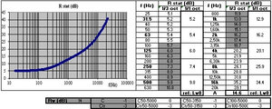
The main result of the acoustic attenuation modeling for the wall in question is, in the compact format required by current standards: Rw(C;Ctr) = 14(-1;-3)
The output data above, regarding the sound reduction index, are comparable to the results of standardized measurements:
- sound reduction index for diffuse (random) incidence, Rstat: cf. ISO 140-3 Acoustics - Measurement of sound insulation in buildings and of building elements - Part 3: Laboratory measurement of airborne sound insulation of building elements
- weighted sound reduction index Rw and correction terms C and Ctr: cf. ISO 717-1 Acoustics - Rating of sound insulation in buildings and of building elements – Part 1: Airborne sound insulation
When working in an acoustics consultancy, or in a company department in charge of development e.g. in R&D context or of the sizing of soundproofing equipment, one does not need every day to evaluate the sound transmission loss of a 10 cm thick foam layer. Such a need might arise, however, for someone considering using this foam as sound-absorbing lining for the splitter baffles of a rectangular silencer, and wondering whether to insert a metal plate (e.g. a steel plate ?) at the baffle's mid-plane, if sound transmission through the foam needs to be limited - because undesirable for the silencer's effectiveness - (the metal plate would then compensate too great a weakness of the foam in terms of sound reduction).
More generally, a similar calculation of the sound reducion index for a layer of porous material (albeit of a different type, such as rock wool) could prove useful to someone selecting what is commonly known as a sound barrier i.e. a mineral wool panel installed vertically above office partitions and extending through the plenum space (spanning the full height up to the floor slab above) to prevent privacy issues regarding conversations.
In France, during the 1990s, massive noise barriers, stretching seemingly endlessly and reaching heights of around fifteen meters (from floor to roof) or more, were installed between building bays in several huge industrial boilermaking workshops (which were independent in terms of their organizational structures, locations, and production outputs). The upper section was constructed by placing two medium-density rock wool panels back-to-back; this raised the question of whether their sound reduction was sufficient or if - once again - a metal sheet needed to be inserted to compensate for any potential performance limitations.
In such contexts, it is essential to know the sound reduction index of porous materials, even when relevant data has not been published. Anyone is free to view the SILDIS® software as a reliable tool, for evaluating in just a few clicks (and, depending on the version, potentially using embbeded libraries of referenced materials with laboratory-measured characteristics that the user can select), performance indicators such as the sound reduction index of materials and partitions.
[0] Sound Impact Limitation - Design for Industrialized Solutions
[2] cf. Modeling the sound absorption of a soundproofing material using SILDIS® software: an example