General information regarding the prediction of insertion loss, transmission loss, and self-noise of reactive silencers (mufflers) using SILDIS® software
Module 1B of the SILDIS®[0] software (in Excel format) enables the predictive calculation of insertion loss, transmission loss, and self-noise (generated by the flow of the conveyed fluid) for reactive silencers (mufflers) i.e. silencers (muffler) whose effectiveness relies not on sound-absorbing lining (as is the case with dissipative silencers), but on sound wave reflection phenomena associated with factors such as changes in waveguide cross-section (e.g. sudden expansion or contraction) and/or the presence of a rigid end-cap that reverses the gas flow (creating a resonator effect).
This module facilitates the sizing of soundproofing products (the SILDIS® software and the engineering work carried out by ITS using SILDIS® have been regularly assessed as compliant with ISO 9001 requirements since 2015):
- within the scope of engineering projects
- within the scope of Research and Development (R&D)
It can be used:
- by ITS personnel responsible - in addition to performing calculations with the software in various contexts - for programming, marketing, training, and support ("internal use")
- by external users, then with reduced functionality (e.g. at their request), in order to minimize questions from potentially inexperienced users regarding input data, model selection, and settings, and to optimize user-friendliness ("external use")
Accordingly, a distinction is drawn below between the two modes of use -"internal use" and "external use" -though this distinction is not rigid or definitive, as the partial lifting of the feature restriction may be considered in certain cases.
For "external use", referring to devices that reduce acoustic transmission within a duct, pipe, or opening (without obstructing fluid flow), the acoustic performance of reactive silencers is typically expressed as the difference between two sound power levels (ordinarily expressed in dB re 1 pW, using the notation found in the SILDIS® software):
For insertion loss:
Lw0 without the silencer ("with zero silencers"), which is an input for calculations
Lw1 with the silencer ("with 1 silencer"), calculated using the formula Lw1 = 10 · log [10^(0.1 · (Lw0 - Di’)) + 10^(0.1 · Lw)]; where Di' is the insertion loss excluding self-generated noise (in dB) and Lw is the sound power level of the noise caused by fluid flow (self-generated noise) in dB re 1 pW
The insertion loss accounting for self-generated noise, Di, is calculated using the relationship Di = Lw0 - Lw1 (expressed in dB).
For transmission loss:
Lw0 upstream of the silencer, which is an input value for the calculations
Lw1 downstream of the silencer, calculated using the formula Lw1 = 10 · log [10^(0.1 · (Lw0 - TL’)) + 10^(0.1 · Lw)]; where TL' is the transmission loss excluding self-generated noise (in dB) and Lw is the sound power level of the noise due to fluid flow (self-generated noise) in dB (ref. 1 pW)
The transmission loss accounting for self-generated noise, TL, is calculated using the relationship TL = Lw0 - Lw1 (expressed in dB).
Calculations are performed within the 20 Hz - 20 kHz frequency range using 1/21-octave bands, which form the basis for the displayed curves. Values for one-third-octave bands (center frequencies from 20 Hz to 20 kHz) and octave bands (center frequencies from 31.5 Hz to 16 kHz) are presented in tabular form. Overall A-weighted values - expressed in dB(A) - are calculated relative to the reference spectrum (Lw0, defined by the user in 1/3-octave or octave bands within the "in COALA-1B" Excel sheet).
Input data can be selected by the user:
- either by entering numerical values (as the software operates in Excel format, this is done in designated cells highlighted in yellow)
- or by selecting a model from a drop-down menu for various stages of the calculations
Regarding the names of the Excel worksheets in the workbook that make up the module(s) of the SILDIS® program (depending on the considered version), those with names beginning with:
- "in": allow for user data input
- "out": allow for the viewing of output data (e.g. calculation results)
- "in-out": allow for both data input and the viewing of output data (e.g. calculation results)
|
Figure 0 Overview of the Excel spreadsheets involved in reactive silencers calculations using Module 1B of the SILDIS® software, for "external use" |
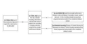
Main aspects for the predictive calculation of insertion loss, transmission loss, and self-noise of reactive silencers (mufflers) using SILDIS® software
Computation-scheme (block-diagram) for the predictive calculation of insertion loss, transmission loss and self-noise of dissipative silencers (mufflers) using SILDIS® software
The computation scheme (block digram aka functional diagram for the predictive calculation of the insertion loss, transmission loss and self-noise of dissipative silencers using SILDIS® software is as shown in Figure 1:
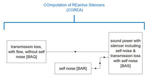
Figure 1 Functional diagram for the predictive calculation of insertion loss, transmission loss and self-noise of dissipative silencers using SILDIS® software
Methodology for the predictive calculation of insertion loss, transmission loss, and self-noise of reactive silencers (mufflers) using SILDIS® software
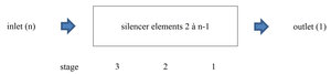
The SILDIS® software enables the predictive calculation of insertion loss, transmission loss, and self-noise (generated by the flow of the transported fluid) for reactive silencers using a transfer matrix method (involving acoustic pressure and mass flow rate) for cascaded elements (see Figure 2):
- interposed between the silencer inlet (numbered n) and the silencer outlet (numbered 1)
- numbered from the outlet to the inlet, from 2 to n-1
- grouped into stages, with the stages numbered from the outlet to the inlet, from 1 to 3
|
Figure 2 Cascaded matrix element numbering for reactive silencer modeling using SILDIS® software |
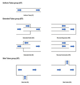
In September 2026, for "external use," these elements are (as illustrated in Figure 3):
- uniform tubes (UT)
- extended tubes (ET)
- side tubes (ST)
|
Figure 3 Element groups for reactive silencer sizing using SILDIS® software: uniform tubes (UT), extended tubes (ET), and side-branch tubes (ST) |
The software enables performance simulations and sizing for various combinations (type, number, and position) of these elements, referred to as "mountings". This term - used since time immemorial during the programming of the SILDIS® software and the drafting of related documentation, and thus retained for the sake of overall consistency, including with regard to current and future additions - should be understood as meaning "configurations."
For each mounting, the dimensions entered by the user are summarized in a diagram displayed on a dedicated Excel sheet.
As of September 2026, the reactive silencers that can be modeled for "external use" are single, double, or triple expansion chambers (without perforated tubes):
- with axial inlet and outlet
- with radial (side) inlet and axial outlet
- with axial inlet and radial (side) outlet
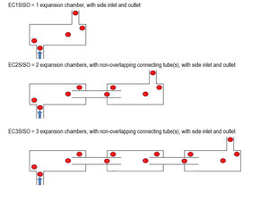
- with radial inlet and outlet
Figure 4 illustrates the various mountings involving single, double, or triple expansion chambers with axial inlet and outlet.
|
Figure 4 Single, double, or triple in-line expansion chamber models using SILDIS® software |
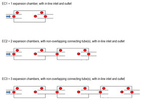
Figure 5 illustrates the various mountings involving single, double, or triple expansion chambers with radial (side) inlets.
|
Figure 5 Single, double, or triple expansion chamber models with radial (side) inlet using SILDIS® software |
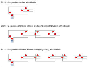
Figure 6 illustrates the various mountings involving single, double, or triple expansion chambers with a radial (side) outlet.
|
Figure 6 Single, double, or triple expansion chamber models with radial (side) outlet using SILDIS® software |
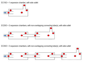
Figure 7 illustrates the various configurations for single, double, or triple expansion chambers with radial (side) inlet and outlet.
|
Figure 7 Single, double, or triple expansion chamber models with radial (side) inlet and outlet, using SILDIS® software |
Summary of configurations for the predictive calculation of insertion loss, transmission loss, and self-noise (generated by the flow of the transported fluid) for reactive silencers without perforated tubes, and summary of the Excel worksheets used to list dimensions entered by the user for "external use," depending on the software version (Table 1)
| Mounting | EC1 | EC2 | EC3 | EC1SI | EC2SI | EC3SI | EC1SO | EC2SO | EC3SO | EC1SISO | EC2SISO | EC3SISO |
| Number of chambers | 1 | 2 | 3 | 1 | 2 | 3 | 1 | 2 | 3 | 1 | 2 | 3 |
| Inlet | Axial | Axial | Axial | Radial (side) | Radial (side) | Radial (side) | Axial | Axial | Axial | Radial (side) | Radial (side) | Radial (side) |
| Outlet | Axial | Axial | Axial | Axial | Axial | Axial | Radial (side) | Radial (side) | Radial (side) | Radial (side) | Radial (side) | Radial (side) |
| Excel sheet for displaying dimensions entered by the user | out EC1 | out EC2 | out EC3 | out EC1SI | out EC2SI | out EC3SI | out EC1SO | out EC2SO | out EC3SO | out EC1SISO | out EC2SISO | out EC3SISO |
Input data for the predictive calculation of insertion loss, transmission loss, and self-noise of reactive silencers (mufflers) using SILDIS® software
Input data can be selected by the user:
- either by entering numerical values (since the software is in Excel format: in designated cells highlighted in yellow)
- or by selecting a model from a drop-down menu for various stages of the calculations
Input data for the predictive calculation of insertion loss and self-generated noise for dissipative silencers using the SILDIS® software must be entered into two separate Excel sheets:
- the "in COALA-1B" Excel sheet
- the "in COSIL-1B" Excel sheet
Thus, for "external use" (assuming clean, dry air) - and without prejudice to the specific characteristics of cascaded silencer elements required for the intended application - the input data to be entered into the "in-COALA-1B" Excel sheet are:
- upstream atmospheric temperature
- upstream atmospheric pressure
- frequency spectrum of the noise to be attenuated (sound power level Lw0)
Other input data must be entered into the "in COSIL-1B" Excel sheet.
General input data - i.e. common to all mountings - for the predictive calculation of insertion loss, transmission loss, and self-noise of reactive silencers (mufflers) using SILDIS® software
General input data - i.e. common to all mountings - must be entered in the "in COSIL-1B" Excel sheet, in the upper section of the table:
- the mass flow rate value (displaying the fluid density allows this input value to be calculated - where useful- in cases where only the volumetric flow rate is explicitly known)
- the silencer inlet diameter
- a general model for flow-generated sound power (to calculate a single, overall value for clean, dry air at ambient conditions) Lwa (dB)
- a model for thermodynamic correction (to adjust this value based on fluid characteristics at operating conditions) C1 (dB)
- a model for spectral correction (to obtain levels for the various frequency bands) C2 (dB)
The sound power level of the self noise (due to the flow) is calculated per octave frequency band using the formula Lw = Lwa + C1 + C2 (dB), with Lwa, C1, and C2 as defined above.
Summary of models common to all envisaged mountings, to be entered into the "in COSIL-1B" Excel worksheet for the predictive calculation of self-generated noise (due to the flow of the transported fluid) of reactive silencers (mufflers) for "external use" (Table 2)
| Parameter | Models |
| General models for flow sound (acoustic) power (Lwa) |
2081a |
| Models for thermodynamic correction (C1) | 3733a 3733b 3733c for conditions other than ambiant ZER i.e. ZERo: for ambiant conditions |
| Models for spectral correction (C2) | 2081a 2081b 2081c 2081d 2081e 3733a 3733b 3733c |
For an "external use," the recommended model(s) are those that are both underlined and displayed in bold in the table above.
Mounting-specific input data, regarding the selection of the mouting and of chambers type, for the predictive calculation of insertion loss, transmission loss, and self-noise of reactive silencers (mufflers) using SILDIS® software
Mounting-specific input data, regarding the selection of the moutning and of the chambers type must be entered in the "in COSIL-1B" Excel sheet, in the upper section of the table:
- a model for the mounting (see Table 1); this selection triggers the use of the appropriate matrix elements and the multiplication of matrices in the correct order
- a sub-model for the chamber(s) type, for each stage
Summary of chamber sub-models for the predictive calculation of insertion loss and transmission loss for reactive silencers without perforated tubes intended for "external use," depending on the software version considered (Table 3)
| Stage | 3 | 2 | 1 |
| Sub-models for chamber(s) type | REA DIS |
REA DIS |
REA DIS |
For an "external use," the recommended model(s) are those that are both underlined and displayed in bold in the table above.
Mounting-specific input data, regarding transfer MATrices, excluding length CORrection settings, for the predictive calculation of insertion loss, transmission loss, and self-noise of reactive silencers (mufflers) using SILDIS® software
For each mounting, the input data regarding transfer MATrices, excluding length CORrection settings, must be entered into the "in COSIL-1B" Excel sheet, in the (vertically) middle section of the table:
- chamber dimensions and - where applicable - the number of connecting tubes:
- small diameter dS (m)
- large diameter dL (m)
- where applicable: number of connecting tubes between chambers 3 & 2
- where applicable: number of connecting tubes between chambers 2 & 1
- total chamber length L (m)
- tube thickness e (m)
- parameters relating to each element of the selected assembly
- geometric length Lx (m) eventually accounting the geometric tuning length for assemblies EC1, EC2, and EC3: Lx_tun (m) which depends on the choice of added length model (this choice must therefore be made first)
- where applicable: a sound attenuation model for elements of the ET group (Extended Tubes)
- a binary indicator (0/1) determining whether or not to apply an end correction to adjust the length
Summary of sub-models for sound attenuation by ET-group elements (Extended Tubes) for the predictive calculation of insertion loss and transmission loss of reactive silencers (mufflers) without perforated tubes intended for "external use," depending on the software version (Table 4)
| Parameter | Models |
| Sound attenuation models for elements of the ET group (Extended Tubes) |
EXA i.e. EXAct |
For an "external use," the recommended model(s) are those that are both underlined and displayed in bold in the table above.
Mounting-specific input data regarding length CORrections for the predictive calculation of insertion loss, transmission loss of reactive silencers (mufflers) using SILDIS® software
Mounting-specific input data regarding length CORrections must be entered in the "in COSIL-1B" Excel sheet, in the lower section of the table:
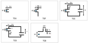
- a model for length addition (cf. figure 8)
- Termination Open Unflanged (TOU)
- Termination Open Flanged (TOF)
- Termination Connected-Coaxial (TCC)
- Termination Connected-Staggered (TCS)
- Termination for Connected with Branch (TCB)
- where applicable (for some models): model specific settings
- a model accounting for the influence of flow
Summary of models regarding length CORrection for the predictive calculation of insertion loss and transmission loss of reactive silencers (mufflers) without perforated tubes for "external use," depending on the software version (Table 5: Termination Open Unflanged (TOU)) (cf. figure 8)
| Model | TOU1 | TOU2 | TOU3 |
| Parameters (besides frequency) | dS/2 | dS/2 | dS/2 |
For an "external use," the recommended model(s) are those that are both underlined and displayed in bold in the table above.
Summary of models regarding length CORrection for the predictive calculation of insertion loss and transmission loss of reactive silencers (mufflers) without perforated tubes for "external use," depending on the software version (Table 5: Termination Open Flanged (TOF))(cf. figure 8)
| Model | TOF1 | TOF2 | TOF3 | TOF4 | TOF5 |
| Parameters (besides frequency) | dS/2 | dS/2 | dS/2 | dS/2 | dS/2 |
For an "external use," the recommended model(s) are those that are both underlined and displayed in bold in the table above.
Summary of models regarding length CORrection for the predictive calculation of insertion loss and transmission loss of reactive silencers (mufflers) without perforated tubes for "external use," depending on the software version (Table 5: Termination Connected-Coaxial (TCC)) (cf. figure 8)
| Model | TCC1 | TCC2 | TCC3 | TCC4 | TCC5 | TCC6 | TCC7 | TCC8 | TCC9 | TCC10 | TCC11 |
| Parameters (besides frequency) |
dS/2 |
dS/2 dL/2 |
dS/2 dL/2 |
dS/2 dL/2 |
dS/2 dL/2 |
dS/2 dL/2 |
dS/2 dL/2 |
dS/2 |
dS/2 dL/2 |
dS/2 dL/2 |
dS/2 |
For an "external use," the recommended model(s) are those that are both underlined and displayed in bold in the table above.
Summary of models regarding length CORrection for the predictive calculation of insertion loss and transmission loss of reactive silencers (mufflers) without perforated tubes for "external use," depending on the software version (Table 5: Termination Connected-Staggered (TCS)) (cf. figure 8)
| Modèle | TCS1 |
| Parameters (besides frequency) | dS/2 dL/2 x |
For an "external use," the recommended model(s) are those that are both underlined and displayed in bold in the table above.
Summary of models regarding length CORrection for the predictive calculation of insertion loss and transmission loss of reactive silencers (mufflers) without perforated tubes for "external use," depending on the software version (Table 5: Termination for Connected with Branch (TCB)) (cf. figure 8)
| Model | TCB1 | TCB2 | TCB3 | TCB4 | TCB5 | TCB6 | TCB7 | TCB8 | TCB9 |
| Parameters (besides frequency) |
dS/2 |
dS/2 dHR/2 |
dS/2 dHR/2 |
dS/2 dHR/2 |
dS/2 dHR/2 |
dS/2 dHR/2 |
dS/2 dHR/2 |
dS/2 dHR/2 |
dS/2 dHR/2 |
For an "external use," the recommended model(s) are those that are both underlined and displayed in bold in the table above.
Figure 8 below presents an overview of added-length models (end corrections) for predicting the acoustic performance of reactive silencers using SILDIS® software.
|
Figure 8 Overview of added-length (end correction) models for predicting the acoustic performance of reactive silencers using SILDIS® software |
Summary of models regarding the influence of flow on length CORrection for the predictive calculation of insertion loss and transmission loss of reactive silencers (mufflers) without perforated tubes for "external use," depending on the software version (Table 6)
| Parameter | Models |
| Influence of flow |
L (Low influence) |
For an "external use," the recommended model(s) are those that are both underlined and displayed in bold in the table above.
Results of the predictive calculation of insertion loss, transmission loss, and self-noise calculations of reactive silencers (mufflers) using SILDIS® software
The results obtained from predicting the insertion loss, transmission loss and self-noise of reactive silencers using SILDIS® software are, in Excel worksheet "in-out CODIS-1B":
- comparable to standardized measurements i.e. ISO 7235, which specifies laboratory measurement procedures for ducted silencers and terminal units (for case studies involving air at ambient temperature and pressure)
- suitable for case studies involving much more demanding sizing requirements
- complemented by an assessment of total pressure loss (as outlined in the aforementioned standard), which characterizes aerodynamic performance, going hand in hand with acoustic performance when evaluating the pros and cons of a silencer design, as soon as flow rate is not zero
A selection regarding the display of results must be made in the "in-out CODIS-1B" Excel sheet: model for the silencer's intrinsic acoustic performance indicator ΔL:
- transmission loss (TL)
- insertion loss (Di)
- sound pressure level difference at a specified location downstream of the silencer (NR)
Summary of models for intrinsic acoustic performance indicator used to predict insertion loss and transmission loss for reactive silencers (mufflers) for an "external use" (Table 7)
| Paramètre | Models |
| Intrinsic acoustic performance indicator ΔL: |
TL |
For an "external use," the recommended model(s) are those that are both underlined and displayed in bold in the table above.
The main output data are as follows:
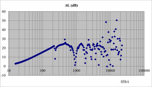
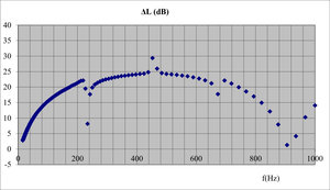
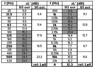
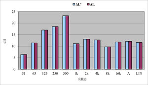
- the silencer's intrinsic acoustic performance indicator ΔL' - i.e., TL', IL', Ilsd', or NR', depending on the selected display model - excluding self-generated noise ΔL' (see Figures 8, 9, 10, 12)
- curves, graphs, and tables: by 1/3-octave and 1/1-octave frequency bands (as well as an A-weighted overall value, calculated based on the reference noise spectrum Lw0)
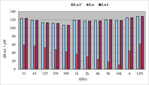
- self-generated noise (sound power level of flow-induced noise) (see Figure 11)
- graphs and tables: by 1/1-octave frequency bands (as well as an A-weighted overall value)
- sound power level with silencer Lw1 (see Figure 11)
- graphs and tables: by 1/1-octave frequency bands (as well as an A-weighted overall value) the silencer's intrinsic acoustic performance indicator ΔL - i.e., TL, IL, Ilsd, or NR, depending on the selected display model - (see Figure 12)
- curves, graphs, and tables: by 1/1-octave frequency bands (as well as an A-weighted overall value, calculated based on the reference noise spectrum Lw0)
|
Figure 8 Transmission loss of a reactive silencer (muffler) with a single expansion chamber modeled using SILDIS® software: results curve for the 20 Hz - 20 kHz |
|
Figure 9 Transmission loss of a reactive silencer (muffler) with a single expansion chamber modeled using SILDIS® software: results curve for the 20 Hz – 1 kHz frequency range |
|
Figure 10 Transmission loss of a reactive silencer (muffler) with a single expansion chamber modeled using SILDIS® software: results table |
|
Figure 11 Comparison of sound power levels upstream and downstream of a reactive silencer (muffler) with a single expansion chamber, modeled using SILDIS® software. |
|
Figure 12 Comparison of the transmission loss of a reactive silencer (muffler) with a single expansion chamber modeled using SILDIS® software: without and with consideration of self-noise. |
[0] Sound Impact Limitation - Design for Industrialized Solutions
 |
|