General information on predicting noise transmission through duct/pipe walls using SILDIS software
The SILDIS[0] software (in Excel format) enables the prediction of noise transmission through the walls of ducts and pipe networks:
- for Heating, Ventilation, and Air Conditioning (HVAC) systems, under standard temperature and pressure conditions in rooms potentially occupied by people
- for pressurized fluid (gas) systems
The term "duct/pipe" is used consistently throughout this article to maintain coherence, referring - depending on the context - not only to the equipment primarily denoted by the words themselves but also, by extension, to a tube, piping element, conduit, or line, as well as anything resembling an enveloppe used for transporting a fluid.
Various sound power levels ordinarily expressed in dB ref. 1 pW must be considered (using the notation found in the SILDIS software):
- Lw0 inside the duct/conduit, which serves as input data for calculations
- for noise transmission from the INside to the OUTside: Lwout = Lw0 - TLout + Kout, where Kout is a correction term (dB)
- for noise transmission from the OUTside to the INside: Lwin = Lw0 - TLin + Kin, where Kin is a correction term (dB)
Two situations must be distinguished, depending on the type of wall involved:
- for a metal sheet (i.e. a thin metallic plate), intrinsic acoustic performance is expressed in terms of the sound reduction index Rdif (in a pseudo-diffuse field), in dB
- for noise transmission from the INside to the OUTside, the following formula is used: TLout = Rdif (dB), where TLout is the (sound) transmission loss in dB
- for noise transmission from the OUTside to the INside, the following formula is used: TLin = Rdif (dB), where TLin is the (sound) transmission loss in dB
- for a metal sheet (i.e. a thin metallic plate) with an external lagging, intrinsic acoustic performance is expressed in terms of transmission loss:
- for noise transmission from the INside to the OUTside, the following formula is used: TLout = Rdif + ILstat (dB), where ILstat is the insertion loss of the lagging (dB)
- for noise transmission from the OUtside to the INside, the following formula is used: TLin = Rdif + ILstat (dB), where ILstat is the insertion loss of the lagging (dB)
Another page on this site[1] provides detailed information regarding:
- the characteristics considered for each material layer (type, model(s), thickness, temperature)
- the software's modeling capabilities
- the naming conventions for Excel sheets used for data input, output data visualization (e.g. calculation results), or both tasks combined
- the "internal use" or "external use" modes of operation
Thus, for both "internal use" and "external use," the input data to be entered are:
- in the "in-COALA" Excel sheet (and, where applicable - for certain special plates - in other related sheets): data concerning the characteristics listed above and the frequency spectrum of the noise to be attenuated (i.e. the sound power level Lw0); regarding materials, the following sets and layers are involved:
- for the sound reduction index of walls without external lagging (Rdif): set 0 (i.e. 1 thin plate), the characteristics of which can be selected using those of set 2 (and the toggle button between set 1 and set 2)
- for the insertion loss of an external lagging (ILstat): the porous medium of set 1 for the insulation, and the thin plate of set 1 for the outer layer
For both "internal use" and "external use", predicting noise transmission through duct or pipe walls involves the use of various Excel worksheets, depending on standard needs for displaying performance indicators.
Summary of Excel worksheets regarding the prediction of noise transmission through duct walls using SILDIS software for "internal use" and "external use" (Table 1)
| Excel worksheet | Duct/pipe cross-section | Direction of noise transmission | Displayed performance indicator |
| in-out CORED IN->OUT | RECtangular |
from INside to OUTside |
Sound reduction index Rdif (for 1 platel of set 0) Lagging insertion loss ILstat (relative to the plate of set 0); with the porous medium of set 1 and with 1 thin plate of set 1 Sound transmission loss TLout (for 1 plate of set 0: with or without the lagging characterized by its insertion loss ILstat) Transmitted sound power level Lwout (with 1 plate from set 0: with or without the lagging characterized by its insertion loss ILstat) |
| in-out CORED OUT->IN | RECtangular | from OUTside to INside | Sound reduction index Rdif (for 1 platel of set 0) Lagging insertion loss ILstat (relative to the plate of set 0); with the porous medium of set 1 and with 1 thin plate of set 1 Sound transmission loss TLin (for 1 plate of set 0: with or without the lagging characterized by its insertion loss ILstat) Transmitted sound power level Lwin (with 1 plate from set 0: with or without the lagging characterized by its insertion loss ILstat) |
| in-out COCID IN->OUT | CIrcular |
from INside to OUTside
|
Sound reduction index Rdif (for 1 platel of set 0) Lagging insertion loss ILstat (relative to the plate of set 0); with the porous medium of set 1 and with 1 thin plate of set 1 Sound transmission loss TLout (for 1 plate of set 0: with or without the lagging characterized by its insertion loss ILstat) Transmitted sound power level Lwout (with 1 plate from set 0: with or without the lagging characterized by its insertion loss ILstat) |
| in-out COCID OUT->IN | CIrcular |
from OUTside to INside
|
Sound reduction index Rdif (for 1 platel of set 0) Lagging insertion loss ILstat (relative to the plate of set 0); with the porous medium of set 1 and with 1 thin plate of set 1 Sound transmission loss TLin (for 1 plate of set 0: with or without the lagging characterized by its insertion loss ILstat) Transmitted sound power level Lwin (with 1 plate from set 0: with or without the lagging characterized by its insertion loss ILstat) |
Calculations are performed within the 20 Hz - 20 kHz frequency range using 1/21-octave bands, which form the basis for the displayed curves. Values for one-third-octave bands (center frequencies from 20 Hz to 20 kHz) and octave bands (center frequencies from 31.5 Hz to 16 kHz) are presented in tabular form.
With reference to Table 1 above, regarding the prediction of noise transmission through duct/pipe walls using the SILDIS software, the following distinctions are made:
- a first distinction based on whether the duct cross-section is REctangular or CIrcular (2 possibilities)
- a second distinction based on whether noise transmission occurs from the INside of the duct to the OUTtside, or in the reverse direction (i.e. from the OUTside to the INside) (2 possibilities)
Consequently, each of the three chapters (procedures diction methodology, input data, and results) comprises a total of four subchapters (combining the two sets of two possibilities mentioned above).
Procedures for predicting noise transmission through duct/pipe walls using SILDIS software
Procedures for predicting noise transmission through rectangular duct/pipe walls using SILDIS software, from INside to OUTside
The flow rate of the transported fluid is not taken into account.
Noise transmission through the walls of rectangular ducts/pipes, from the INside to the OUTside can be predicted using the SILDIS software in the following ways:
- by taking into account the material of the base wall (thin plate from set 0) as entered in the "in-COALA" Excel sheet, and the cross-sectional dimensions of the duct as entered in the "in-out CORED IN->OUT" Excel sheet (which is also used for the "in-out CORED OUT->IN" sheet)
- without taking into account the material of the base wall (thin plate from set 0) as entered in the "in-COALA" Excel sheet (in which case a steel sheet is assumed) and without taking into account the cross-sectional dimensions of the duct/pipe
Predicting noise transmission through the walls of rectangular ducts from the inside to the outside using the SILDIS software involves the use of specific models and settings at various stages of the calculations.
Summary of models for predicting the sound reduction index (Rdif) of rectangular duct/pipe walls using the "in-out CORED IN->OUT" Excel sheet in the SILDIS software for "external use" accounting for the wall material (as entered in the "in-COALA" Excel sheet) and the duct/pipe's cross-sectional dimensions.
| Parameter | Cut-off frequency (fco) | Cross-over frequency (fcr) | For f < fcr noise transmission | For f > fcr noise transmission | Minimum for Rdif | Maximum for Rdif |
| Models |
HAN |
HAN |
HAN |
HAN NAS SMA |
HAN ZER |
HAN NAT |
For an "external use" the recommended model(s) are those that are both underlined and displayed in bold in the table above.
Summary of models for predicting the sound reduction index (Rdif) of rectangular duct/pipe walls within the "in-out CORED IN->OUT" Excel sheet of the SILDIS software for "external use," disregarding the wall material specified in the "in-COALA" Excel sheet (assuming sheet steel instead) and disregarding the duct/pipe cross-sectional dimensions
| Parameter | Minimum for Rdif |
| Models |
HAN |
For an "external use" the recommended model(s) are those that are both underlined and displayed in bold in the table above.
Summary of models for predicting the insertion loss (ILstat) of external cladding on rectangular ducts/conduits, based on the "in-out CORED IN->OUT" Excel sheet in the SILDIS software for "external use."
| Parameter | ILstat |
| Models |
RIG |
For an "external use" the recommended model(s) are those that are both underlined and displayed in bold in the table above.
Summary of models for predicting sound transmission loss (TLout) of rectangular ducts with external lagging, in the "in-out CORED IN->OUT" Excel sheet of the SILDIS software for "external use"
| Parameter | Rdif | Consideration of IL stat (0/1) |
| Models |
1 (taking into account the nature of the wall material as entered in the "in-COALA" Excel sheet) |
0 1 |
For an "external use" the recommended model(s) are those that are both underlined and displayed in bold in the table above.
Summary of models for predicting the sound power level (Lwout) transmitted through rectangular duct walls with or without external lagging in the "in-out CORED IN->OUT" Excel sheet of the SILDIS software for "external use" (HVAC systems)
| Parameter | Lwout |
| Models |
2081 |
For an "external use," the recommended model(s) are those that are both underlined and displayed in bold in the table above.
Summary of models for predicting the sound power level (Lwout) transmitted through rectangular duct walls with or without external lagging in the "in-out CORED IN->OUT" Excel sheet of the SILDIS software, for "external use" applications: pressurized fluid (gas) networks
| Parameter | Lwout | Diffusivity factor Kd |
| Models |
3733 |
SIN 3 |
For an "external use" the recommended model(s) are those that are both underlined and displayed in bold in the table above.
Procedures for predicting noise transmission through rectangular duct walls using SILDIS software, from OUTside to INside
The flow rate of the transported fluid is not taken into account.
Noise transmission through the walls of rectangular ducts from the OUTside to the INside can be predicted using the SILDIS software in the following ways:
- accounting for the material of the base wall (thin plate from set 0) as entered in the "in-COALA" Excel sheet, and accounting for the duct's cross-sectional dimensions as entered in the "in-out CORED IN->OUT" Excel sheet (which is also used for the "in-out CORED OUT->IN" sheet)
- without accounting for the material of the base wall (thin plate from set 0) as entered in the "in-COALA" Excel sheet (assuming sheet steel instead) and without accounting for the duct's cross-sectional dimensions
The approach is as follows:
- regarding the sound reduction index Rdif:
- first: evaluation of Rdif for transmission direction from the duct/pipe INside to OUTside (one shall usefully refer to the previously described procedures regarding models and settings)
- then: evaluation of Rdif for transmission direction from the duct/pipe OUTside to INside by subtracting a correction term from the previous evaluation
- regarding the insertion loss of a lining (ILstat):
- evaluation identical to that for transmission direction from the duct/pipe INside to OUTside (one shall usefully refer to the previously described procedures regarding models and settings); the reversal of sets 0 and 1 associated with the change in transmission direction is not taken into account in the "in COALA" Excel sheet
- regarding the transmission loss TLin and the transmitted sound power level Lwin
- evaluation as indicated in the § "General information"
In addition to the models and settings relating to sound transmission from the INnside of the duct/pipe to the OUTside which must first be selected as previously described in the "in-out CORED IN->OUT" Excel sheet predicting noise transmission through rectangular duct walls from the OUTside to the INside using SILDIS software requires the use of additional models and settings for various other stages of the calculations.
Summary of complementary models for predicting the sound reduction index (Rdif) of rectangular duct walls using the "in-out CORED OUT->INT" Excel sheet in the SILDIS software for "external use" accounting for the wall material (as entered in the "in-COALA" Excel sheet) and the duct/pipe's cross-sectional dimensions
| Parameter | Cross-over frequency fcr |
| Models |
HAN |
For an "external use" the recommended model(s) are those that are both underlined and displayed in bold in the table above.
Summary of complementary models for predicting the sound reduction index (Rdif) of rectangular duct walls using the "in-out CORED OUT->INT" Excel sheet in the SILDIS software for "external application" without accounting for the wall material specified in the "in-COALA" Excel sheet (assuming sheet steel instead) and without accounting for the duct/pipe's cross-sectional dimensions
| Parameter | a/b ratio which is not calculated by the software based on the duct's largest and smallest dimensions, but is a ratio approximating this |
| Models |
1 |
For an "external use" the recommended model(s) are those that are both underlined and displayed in bold in the table above.
Summary of complementary models for predicting the sound transmission loss (TL_in) of rectangular duct walls in the "in-out CORED OUT->INT" Excel sheet of the SILDIS software for "external use."
| Parameter | Rdif |
| Models |
1 i.e. taking into account the nature of the wall material as entered in the "in-COALA" Excel sheet (thin plate from set 0) and the cross-sectional dimensions of the duct/pipe |
For an "external use" the recommended model(s) are those that are both underlined and displayed in bold in the table above.
Summary of models for predicting the sound power level (Lwin) transmitted through rectangular duct walls with or without external cladding in the "in-out CORED OUT->INT" Excel sheet of the SILDIS software, for "external use" (HVAC systems)
| Parameter | Lwin |
| Models |
2081 |
For an "external use" the recommended model(s) are those that are both underlined and displayed in bold in the table above.
Procedures for predicting noise transmission through circular duct/pipe walls using SILDIS software, from the INside to the OUTside
The term "spiral-seam duct" is used consistently throughout this article to maintain coherence, referring also to the so-called spiral-wound circular duct.
Using the SILDIS software, the prediction of noise transmission through the walls of circular ducts/pipes from the inside to the outside can be performed:
- for a non-spiral-seam duct (e.g. a pipe); the flow rate of the conveyed fluid is not taken into account
- for a spiral-seam ducts; the flow rate of the conveyed fluid is taken into account
This is performed by accounting for the material properties of the base wall (thin plate from set 0) as entered in the "in-COALA" Excel sheet and by accounting for the duct/pipe's cross-sectional dimension (diameter) and flow rate as entered in the "in-out COCID IN->OUT" Excel sheet (which is also used for the "in-out COCID OUT->IN" Excel sheet).
Predicting noise transmission through the walls of circular ducts/pies from the inside to the outside using SILDIS software involves the use of specific models and settings at various stages of the calculations.
Synthesis of models for predicting the sound reduction index (Rdif) of circular duct/pipe walls in the "in-out COCID IN->OUT" Excel sheet of the SILDIS software for "external use", for a non-spiral-seam duct
| Parameter | Mounting |
| Models |
a) welded pipe with an average of one bend per approximately 20D length |
Synthesis of models for predicting the sound reduction index (Rdif) of circular duct/pipe walls in the "in-out COCID IN->OUT" Excel sheet of the SILDIS software for "external use", for a spiral-seam duct
| Parameter | Annular expansion frequency (fRokt) | HF limitation (for high frequency) |
| Models |
NAT (NATural, i.e. without replacement by the 1/1-octave band center frequency) |
2081 MOI |
For an "external use" the recommended model(s) are those that are both underlined and displayed in bold in the table above.
Summary of models for predicting the insertion loss (ILstat) of external lagging on circular ducts/pipes in the "in-out COCID IN->OUT" Excel sheet in the SILDIS software for "external use"
| Parameter | ILstat |
| Models |
HAL |
For an "external use" the recommended model(s) are those that are both underlined and displayed in bold in the table above.
Summary of models for predicting sound transmission loss (TLout) of circular ducts/pipes with external lagging in the "in-out COCID IN->OUT" Excel sheet of the SILDIS software for "external use"
| Parameter | Rdif | Consideration of ILstat (0/1) |
| Models |
1 for a non-spiral-seam duct, without taking flow rate into account |
0 1 |
For an "external use" the recommended model(s) are those that are both underlined and displayed in bold in the table above.
Summary of models for predicting the sound power level (Lwout) transmitted through circular duct/pipes walls with or without external lagging in the "in-out COCID IN->OUT" Excel sheet of the SILDIS software for "external use" (HVAC systems)
| Parameter | Lwout |
| Models |
2081 |
For an "external use" the recommended model(s) are those that are both underlined and displayed in bold in the table above.
Summary of models and settings for predicting the sound power level (Lwout) transmitted through circular duct/pipe walls with or without external lagging in the "in-out COCID IN->OUT" Excel sheet of the SILDIS software for "external use" (pressurized fluid/gas networks)
| Parameter | Lwout | Diffusivity factor Kd |
| Models |
3733 |
SIN 3 |
For an "external use" the recommended model(s) are those that are both underlined and displayed in bold in the table above.
Procedures for predicting noise transmission through circular duct/pipe walls from OUTside to INside using SILDIS software
Predicting noise transmission from the outside to the inside through circular duct walls using SILDIS software can be performed:
- for a spiral-seam duct; the flow rate of the conveyed fluid is taken into account (as of September 2026: calculation for non-spiral-seam ducts/pipes pending)
The approach is as follows:
- regarding the sound reduction index Rdif:
- first: evaluation of Rdif for transmission direction from the duct/pipe INside to OUTside (one shall usefully refer to the previously described procedures regarding models and settings)
- then: evaluation of Rdif for transmission direction from the duct/pipe OUTside to INside by subtracting a correction term from the previous evaluation
- regarding the insertion loss of a lining (ILstat):
- evaluation identical to that for transmission direction from the duct/pipe INside to OUTside (one shall usefully refer to the previously described procedures regarding models and settings); the reversal of sets 0 and 1 associated with the change in transmission direction is not taken into account in the "in COALA" Excel sheet
- regarding the transmission loss TLin and the transmitted sound power level Lwin
- evaluation as indicated in the § "General information"
In addition to the models and settings relating to sound transmission from the INnside of the duct/pipe to the OUTside which must first be selected as previously described in the "in-out COCID IN->OUT" Excel sheet predicting noise transmission through rectangular duct/pipe walls from the OUTside to the INside using SILDIS software requires the use of additional models and settings for various other stages of the calculations.
Summary of complementary models for predicting sound transmission loss (TL_in) of circular duct/pipe walls in the "in-out COCID OUT->INT" Excel sheet of the SILDIS software for "external use"
| Parameter | Rdif |
| Models |
1 for a non-spiral-seam duct, without taking flow rate into account |
For an "external use" the recommended model(s) are those that are both underlined and displayed in bold in the table above.
Summary of models for predicting the sound power level (Lwin) transmitted through circular duct/pipe walls with or without external lagging in the "in-out COCID OUT->INT" Excel sheet of the SILDIS software for "external use" (HVAC systems)
| Parameter | Lwin |
| Models |
2081 |
For an "external use" the recommended model(s) are those that are both underlined and displayed in bold in the table above.
Input data for predicting noise transmission through duct/pipe walls using SILDIS software
Input data for predicting noise transmission through duct/pipe walls using SILDIS software must be entered into two separate Excel sheets:
- the "in-COALA" Excel worksheet (e.g. for material-related data)
- one of the Excel worksheets listed in Table 1 above (i.e. in-out CORED IN->OUT, in-out CORED OUT->IN, in-out COCID IN->OUT, or in-out COCID OUT->IN): specifically the one corresponding to the geometry in question (REctangular or CIrcular) and the direction of noise transmission (from the INside of the duct/pipe to the OUTside, or vice versa i.e. from the OUTside to the INside) for the remaining specific input data.
Input data for predicting noise transmission through rectangular duct/pipe walls using SILDIS software from INside to OUTtside
Input data for predicting the sound reduction index Rdif for rectangular duct/pipe walls using SILDIS software, for inside-to-outside sound transmission direction
- in the "in COALA" Excel sheet:
- taking into account the material of the base wall (thin plate from set 0) and the cross-sectional dimensions of the duct/pipe: (reference), density, and thickness of the thin plate from set 0
- without taking into account the material of the base wall (thin plate from set 0) (assuming sheet steel instead) and without taking into account the cross-sectional dimensions of the duct/pipe: thickness of the thin plate from set 0
- in the "out CORED IN->OUT" Excel sheet, in the upper part of the table:
- taking into account the material of the base wall (thin plate from set 0) and the cross-sectional dimensions of the duct/pipe:
- duct dimensions: largest and smallest dimension, length, flow rate (the cut-off frequency model fco is not used for calculations)
- without taking into account the material of the base wall (thin plate from set 0) (assuming sheet steel instead) and without taking into account the cross-sectional dimensions of the duct/pipe:
- none
- in the "out CORED IN->OUT" Excel sheet, in the lower part of the table:
- taking into account the material of the wall and the cross-sectional dimensions of the duct/pipe:
- a transition frequency model fcr, a noise transmission model for f < fcr, a noise transmission model for f > fcr, a minimum value for Rdif, a maximum value for Rdif
- without taking into account the material of the wall (assuming sheet steel instead) and without taking into account the cross-sectional dimensions of the duct/pipe:
- a minimum value model for Rdif
- taking into account the material of the wall and the cross-sectional dimensions of the duct/pipe:
Input data for predicting the insertion loss of a lagging ILstat for rectangular ducts/pipes using SILDIS software, for inside-to-outside sound transmission direction
- in the "in COALA" Excel sheet:
- taking into account the material of the base wall (thin plate from set 0): thickness of the porous medium from set 1; (reference), density and thickness of the thin plate from set 0, and that of set 1
- without taking into account the material of the base wall (thin plate from set 0) (and thus assuming a steel sheet): thickness of the thin plate from set 0, density and thickness of the thin plate from set 1
- in the "in-out CORED IN->OUT" Excel sheet, in the upper part of the table:
- taking into account the cross-sectional dimensions of the duct/pipe:
- duct dimensions: largest and smallest dimension (the cut-off frequency model fco is not considered for the calculations)
- taking into account the cross-sectional dimensions of the duct/pipe:
- in the "in-out CORED IN->OUT" Excel sheet, in the lower part of the table:
- a model: RIG or LIMP
- a limitation of IL at high frequencies, i.e. a limit value for ILstat at high frequencies (dB)
Input data for predicting sound transmission loss TLout and sound power level Lwout for rectangular ducts/pipes, with or without duct wall lagging, using SILDIS software, for inside-to-outside sound transmission direction
- in the "in COALA" Excel sheet:
- nothing different from Rdif and ILstat (cf. above)
- in the "in-out CORED IN->OUT" Excel sheet, in the upper part of the table:
- nothing different from Rdif and ILstat (cf. above)
- in the "in-out CORED IN->OUT" Excel sheet, in the lower part of the table:
- a Rdif selection model:
- 1 if the nature of the base wall material (thin plate from set 0) and the cross-sectional dimensions of the duct/pipe are taken into account
- 2 if the nature of the base wall material (thin plate from set 0) and the cross-sectional dimensions of the duct/pipe are not taken into account
- a binary choice (1 for yes, 0 for no) regarding whether or not to include ILstat
- for an HVAC (Heating, Ventilation, and Air Conditioning) system: a model for Lwout, a sound attenuation spectrum (Δ dB/m) reflecting internal system losses
- for a pressurized fluid system: a model for Lwout, a model for the diffusivity factor Kd=Km, and a value for the (total) duct length l (m)
- a Rdif selection model:
Input data for predicting noise transmission through rectangular duct/pipe walls using SILDIS software from outside to inside
Input data for predicting the sound attenuation index Rdif for rectangular duct/pipe walls using SILDIS software, for outside-to-inside sound transmission direction
- in the "in COALA" Excel sheet and in the "in-out CORED IN->OUT" Excel sheet:
- the input data listed above for transmission from the inside to the outside
- in the "in-out CORED OUT->IN" Excel sheet, in the lower part of the table:
- taking into account the material of the wall and the cross-sectional dimensions of the duct/pipe:
- critical frequency model (fcr)
- without taking into account the material of the wall (assuming sheet steel instead) and without taking into account the cross-sectional dimensions of the duct/pipe:
- an a/b ratio model (ratio of the largest duct/pipe dimension to the smallest)
- taking into account the material of the wall and the cross-sectional dimensions of the duct/pipe:
Input data for predicting the insertion loss of a lagging ILstat for rectangular ducts/pipes using SILDIS software, for outside-to-inside sound transmission direction
- in the Excel sheet "in COALA" and in the Excel sheet "n-out CORED IN->OUT":
- the input data listed above for the direction of transmission from the inside to the outside
- in the Excel sheet "in-out CORED OUT->IN", at the bottom of the table:
- none
Input data for predicting sound transmission loss TLin and sound power level Lwin with or without duct/pipe wall lagging for rectangular ducts using SILDIS software, for outside-to-inside sound transmission direction
- in the "in COALA" Excel sheet and in the "in-out CORED IN->OUT" Excel sheet:
- the input data listed above for the transmission direction from inside to outside
- in the "in-out CORED OUT->IN" Excel sheet, in the lower part of the table:
- a selection model for Rdif:
- 1 if the nature of the base wall material (thin plate from set 0) and the cross-sectional dimensions of the duct/pipe are taken into account
- 2 if the nature of the base wall material (thin plate from set 0) and the cross-sectional dimensions of the duct/pipe are not taken into account
- a binary choice (1 for yes, 0 for no) regarding whether or not to include ILstat
- for an HVAC (Heating, Ventilation, and Air Conditioning) system: a model for Lw
- a selection model for Rdif:
Input data for predicting noise transmission through circular duct/pipe walls using SILDIS software from INside to OUTside
Input data for predicting the sound attenuation index Rdif for circular duct/pipe walls using SILDIS software, for inside-to-outside sound transmission direction
- in the "in COALA" Excel sheet:
- for non-spiral-seam duct (without airflow consideration) or spiral-seam duct (with airflow consideration): (reference), density, and thickness of the thin plate from set 0
- in the "in-out COCID IN->OUT" Excel sheet, in the upper part of the table:
- for non-spiral-seam duct (without airflow consideration) or spiral-seam duct (with airflow consideration): duct dimensions: diameter, length, airflow (the cutoff frequency model fco is not taken into account for the calculations)
- in the "in-out COCID IN->OUT" Excel sheet, in the lower part of the table:
- for non-spiral-seam duct (without airflow consideration):
- model for mounting
- for spiral-seam duct (with airflow consideration):
- an annular expansion frequency model fRokt, a HF limitation model (for high-frequency)
- for non-spiral-seam duct (without airflow consideration):
Input data for predicting the insertion loss of a lagging ILstat for circular ducts using SILDIS software, for inside-to-outside sound transmission direction
- in the "in COALA" Excel sheet:
- for non-spiral-seam duct/pipe (without flow rate consideration) or spiral-seam duct/pipe (with flow rate consideration): material constituting the base wall (thin plate from set 0); thickness of the porous medium from set 1; (reference), density, and thickness of the thin plate from set 0 and that from set 1
- in the "in-out COCID IN->OUT" Excel sheet, in the upper part of the table:
- for non-spiral-seam duct/pipe (without flow rate consideration) or spiral-seam duct/pipe (with flow rate consideration): duct dimensions: diameter, length, flow rate (the cut-off frequency model fco is not taken into account for the calculations)
- in the "in-out COCID IN->OUT" Excel sheet, in the lower part of the table:
- a model: HAL or MIC
Input data for predicting sound transmission loss TLout and sound power level (Lwout) with or without duct wall lagging for circular ducts using SILDIS software, for inside-to-outside sound transmission direction
- in the "in COALA" Excel sheet:
- nothing different from Rdif and ILstat (cf. above)
- in the "in-out COCID IN->OUT" Excel sheet, in the upper part of the table:
- nothing different from Rdif and ILstat (see above)
- in the "in-out COCID IN->OUT" Excel sheet, in the lower part of the table:
- a Rdif selection model:
- 1 for non-spiral-seam duct/pipe (without airflow consideration)
- 2 for spiral-seam duct/pipe (with airflow consideration)
- binary choice (1 for yes, 0 for no) regarding whether or not to include ILstat
- for an HVAC (Heating, Ventilation, and Air Conditioning) system: a model for Lwout, a sound attenuation spectrum (Δ dB/m) reflecting internal system losses
- for a pressurized fluid system: a model for Lwout, a model for the diffusivity factor Kd=Km, and a value for the (total) duct length l (m)
- a Rdif selection model:
Input data for predicting noise transmission through circular duct/pipe walls using SILDIS software, from OUTside to INside
Input data for predicting the sound attenuation index Rdif for circular duct/pipe walls using SILDIS software, for outside-to-inside sound transmission direction
- In the Excel sheet "in COALA" and in the Excel sheet "n-out COCID IN->OUT":
- the input data listed above for the direction of transmission from the inside to the outside
- In the Excel sheet "in-out COCID OUT->IN", at the bottom of the table:
- none
Input data for predicting the insertion loss of a lagging ILstat for circular ducts/pipes using SILDIS software, for outside-to-inside sound transmission direction
- in the Excel sheet "in COALA" and in the Excel sheet "n-out COCID IN->OUT":
- the input data listed above for the direction of transmission from the inside to the outside
- in the Excel sheet "in-out COCID OUT->IN", at the bottom of the table:
- none
Input data for predicting sound transmission loss TLin and sound power level (LWin) with or without duct/pipe wall lagging for circular ducts using SILDIS software, for outside-to-inside sound transmission direction
- in the "in COALA" Excel sheet and the "in-out CORED IN->OUT" Excel sheet:
- the input data listed above for the transmission direction from inside to outside
- in the "in-out COCID OUT->IN" Excel sheet, in the lower part of the table:
- a selection for the Rdif model:
- for non-spiral-seam duct/pipe (without accounting for airflow rate) or spiral duct/pipe; as of September 2026, this option is not available due to the lack of an Rdif evaluation for this transmission direction
- for spiral-seam duct/pipe (accounting for airflow rate)
- binary choice (1 for yes, 0 for no) regarding whether or not to account for ILstat
- for an HVAC (Heating, Ventilation, and Air Conditioning) system: a model for Lwin
- a selection for the Rdif model:
Results of noise transmission prediction through duct/pipe walls using SILDIS software
Results of noise transmission predictions through rectangular duct/pipe walls using SILDIS software, from INside to OUTside: in the Excel sheet "in-out CORED IN->OUT"
Results of the predicted sound reduction index Rdif for rectangular duct/pipe walls using SILDIS software, for inside-to-outside sound transmission direction
- taking into account the material of the base wall (thin plate from set 0) and the cross-sectional dimensions of the duct/pipe:
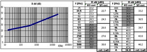
- curves and tables: by 1/3-octave and 1/1-octave frequency bands (as well as A-weighted overall value, calculated relative to the reference noise spectrum Lw0) (cf. figure 1)
- without taking into account the material of the base wall (thin plate from set 0) (assuming sheet steel instead) and without taking into account the cross-sectional dimensions of the duct/pipe:
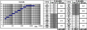
- curves and tables: by 1/3-octave and 1/1-octave frequency bands (as well as A-weighted overall value, calculated relative to the reference noise spectrum Lw0) (cf. figure 2)
Results of the predicted insertion loss ILstat for a lagging of rectangular ducts/pipes using SILDIS software, for inside-to-outside sound transmission
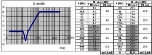
- curves and tables: per 1/3-octave and 1/1-octave frequency bands (as well as A-weighted overall value, calculated relative to the reference noise spectrum Lw0) (cf. figure 3)
Results of the predicted sound transmission loss TLout with or without lagging for rectangular duct/pipe walls using SILDIS software, for inside-to-outside sound transmission
- tables: per 1/1 octave frequency band (as well as A-weighted overall value, calculated relative to the reference noise spectrum Lw0)
Results of the predicted sound power level Lwout with or without lagging for rectangular duct/pipe walls using SILDIS software, for inside-to-outside sound transmission
- tables: per 1/1-octave frequency band (as well as A-weighted overall value)
Results of noise transmission predictions through rectangular duct/pipe walls using SILDIS software, from OUTside to INside: in the Excel sheet "in-out CORED OUT->IN"
Results of the predicted sound reduction index Rdif for rectangular duct/pipe walls using SILDIS software, for outside-to-inside sound transmission
- taking into account the nature of the material constituting the base wall (thin plate from set 0) and the cross-sectional dimensions of the duct/pipe:
- curves and tables: per 1/3-octave and 1/1-octave frequency bands (as well as an overall A-weighted value, calculated relative to the reference noise spectrum Lw0) (cf. figure 1, relating to a reverse transmission direction, which does not alter the general shape of the curve)
- without taking into account the nature of the material constituting the base wall (thin plate from set 0) (assuming sheet steel instead) and without taking into account the cross-sectional dimensions of the duct/pipe:
- curves and tables: per 1/3-octave and 1/1-octave frequency bands (as well as an overall A-weighted value, calculated relative to the reference noise spectrum Lw0) (cf. figure 2, relating to a reverse transmission direction, which does not alter the general shape of the curve)
Results of the predicted insertion loss ILstat for a lagging of rectangular duct/pipe walls using SILDIS software, for outside-to-inside sound transmission
- curves and tables: per 1/3-octave and 1/1-octave frequency bands (as well as A-weighted overall value, calculated relative to the reference noise spectrum Lw0) (cf. figure 3, relating to a reverse transmission direction, which does not alter the general shape of the curve)
Results of the predicted sound transmission loss TLin with or without lagging for rectangular duct/pipe walls using SILDIS software, for outside-to-inside sound transmission
- tables: per 1/1 octave frequency band (as well as A-weighted overall value, calculated relative to the reference noise spectrum Lw0)
Results of the predicted sound power level Lwin with or without lagging for rectangular duct/pipe walls using SILDIS software, for outside-to-inside sound transmission
- tables: per 1/1-octave frequency band (as well as A-weighted overall value)
Results of noise transmission predictions through circular duct/pipe walls using SILDIS software, from INside to OUTside: in the Excel sheet "in-out COCID IN->OUT"
Results of the predicted sound reduction index Rdif for circular duct/pipe walls using SILDIS software, for inside-to-outside sound transmission direction
- for non-spiral-seam ducts/pipes (without considering flow rate):
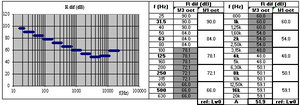
- curves and tables: per 1/3 octave and 1/1 octave frequency bands (as well as the overall A-weighted value, calculated relative to the reference noise spectrum Lw0) (cf. figure 4)
- for spiral-seam ducts/pipes (with considering flow rate):
- curves and tables: per 1/3 octave and 1/1 octave frequency bands (as well as the overall A-weighted value, calculated relative to the reference noise spectrum Lw0) (cf. figure 4, relating to a non-spiral-seam duct/pipe, which does not alter the general shape of the curve)
Results of the predicted insertion loss ILstat for a lagging of circular ducts/pipes using SILDIS software, for inside-to-outside sound transmission
- curves and tables: per 1/3-octave and 1/1-octave frequency bands (as well as A-weighted overall value, calculated relative to the reference noise spectrum Lw0) (cf. figure 3, relating to a rectangular duct, which does not alter the general shape of the curve)
Results of the predicted sound transmission loss TLout with or without lagging for circular duct/pipe walls using SILDIS software, for inside-to-outside sound transmission
- tables: per 1/1 octave frequency band (as well as A-weighted overall value, calculated relative to the reference noise spectrum Lw0)
Results of the predicted sound power level Lwout with or without lagging for circular duct/pipe walls using SILDIS software, for inside-to-outside sound transmission
- tables: per 1/1-octave frequency band (as well as A-weighted overall value)
Results of noise transmission predictions through circular duct walls using SILDIS software, from OUTside to INside): in the Excel sheet "in-out COCID OUT->IN"
Results of the predicted sound reduction index Rdif for circular duct/pipe walls using SILDIS software, for outside-to-inside sound transmission
- for a non-spiral-seam duct/pipe, without accounting for airflow rate:
- curves and tables: per 1/3-octave and 1/1-octave frequency bands (as well as an A-weighted overall value, calculated relative to the reference noise spectrum Lw0); as of September 2026, the displayed values are zero, as no calculation is performed for this direction of transmission
- for a spiral-seam duct/pipes, accounting for airflow rate:
- curves and tables: per 1/3-octave and 1/1-octave frequency bands (as well as an A-weighted overall value, calculated relative to the reference noise spectrum Lw0) (cf. figure 4, relating to the reverse direction of transmission, which does not alter the general shape of the curve)
Results of the predicted insertion loss ILstat for a lagging of circular ducts/pipes using SILDIS software, for ouside-to-inside sound transmission
- curves and tables: per 1/3-octave and 1/1-octave frequency bands (as well as A-weighted overall value, calculated relative to the reference noise spectrum Lw0) (cf. Figure 3, assuming a rectangular duct and reverse transmission direction, which does not alter the general shape of the curve)
Results of the predicted sound transmission loss TLin with or without lagging for circular duct/pipe walls using SILDIS software, for ouside-to-inside sound transmission
- tables: per 1/1 octave frequency band (as well as A-weighted overall value, calculated relative to the reference noise spectrum Lw0)
Results of the predicted sousnd power level Lwin with or without lagging for circular duct/pipe walls using SILDIS software, for ouside-to-inside sound transmission
- tables: per 1/1-octave frequency band (as well as A-weighted overall value)
|
Figure 1 Sound reduction index of a rectangular duct/pipe wall: accounting for cross-sectional dimensions (calculation with SILDIS software) |
|
Figure 2 Sound reduction index of a rectangular duct/pipe wall: without accounting for cross-sectional dimensions (calculation with SILDIS software) |
|
Figure 3 Insertion loss of an external lagging for a rectangular duct/pipe wall (calculation with SILDIS software) |
|
Figure 4 Sound reduction index of thick-walled steel pipe/tube (simulated using SILDIS software) |
[0] Sound Impact Limitation - Design for Industrialized Solutions
[1] cf. Modeling and optimization of multilayer acoustic structures using SILDIS software