The SILDIS® software (Excel) enables the acoustic and aerodynamic sizing of a reactive silencer (muffler) with perforated tube(s) e.g. for a mounting sometimes referred to as a concentric-tube resonator, as illustrated by a case study (Example 1B.4.3 in the User's manual). Such a noise attenuator (here termed "reactive," despite the fact that energy dissipation does indeed occur in the perforations) shares similarities with a simple expansion chamber - for which a calculation example is provided elsewhere[0] in that:
- no sound-absorbing porous material is required for its operation (although such a lining can be useful to complement the performance of a purely reactive silencer, e.g. at mid-to-high frequencies, by adding a purely dissipative stage)
- its effectiveness relies on sound wave reflection caused by changes in waveguide cross-section (e.g. sudden expansion or contraction) and/or the presence of a rigid end-cap that reverses the gas flow (creating a resonator effect)
However, it differs in the following respects:
- its operating principle, which relates to specific - and complex - phenomena associated with the presence of orifices (the drillings in the perforated tube) through which sound propagates - and, where applicable, through which gas flow circulates
- its acoustic performance, which is influenced by the impedance linked to the geometric characteristics of the perforated tube's orifices and the relevant fluid dynamics parameters (e.g. Mach numbers associated with both the grazing flow and the flow passing through the orifices); this effect replaces the sound propagation that would otherwise occur within the waveguide formed by the silencer expansion chamber casing
- its aerodynamic performance, which is affected by the gas flow circulating through the perforated tube's orifices; this effect replaces the sudden expansion at the silencer inlet and the sudden contraction at the outlet (phenomena that would otherwise cause significant total pressure loss)
The bridge formed by the perforated tube - connecting the inlet and the outlet of the expansion chamber - avoids the discontinuity caused - otherwise - by the difference in diameter (between main pipe and expansion chamber body) basing (all the more so when large) the efficiency of a simple expansion chamber, involving turbulences to which total pressure loss and noise generation - both of which being obviously undesirable - are related; a reactive silencer with a perforated tube is generally expected to mitigate these drawbacks.
Like a simple expansion chamber, a reactive silencer (muffler) with a perforated tube exhibits frequency-dependent acoustic performance and, to maximize it across a sufficiently wide frequency band of interest, the device can be "tuned" - meaning its geometry can be purposefully selected, axial dimensions (i.e. lengths) playing a crucial role, as does the ratio of the chamber's diameter to the inlet (and outlet) diameter. Such an optimization of the dimensional parameters of a reactive silencer with a perforated tube is facilitated by a specific software feature, as illustrated below.
Problem statement (envisaged application relating to the computation of a reactive silencer-muffler with a perforated tube using software SILDIS®)
The aim is to calculate the acoustic and aerodynamic performance of a purely reactive silencer (muffler) [1] featuring a simple expansion chamber with a perforated tube - referred to as EC1P1 in the software [2] - with a circular cross-section, an inlet and outlet diameter dS = 50 mm [3], a chamber diameter dL = 150 mm [4], and a length L = 401 mm [5] using the software's optimization features to determine the lengths of the perforated sections at the chamber inlet [6] and outlet [7] (i.e. the La and Lb tuning values automatically displayed by SILDIS®); tube lengths outside the expansion chamber are considered negligible (i.e. set to zero) [8]. The silencer is intended for use with a fluid approximating clean, dry air [9] with a flow rate of 0.080 kg/s [10], a temperature of 30°C [11], and a pressure of 100000 Pa [12]. The reference spectrum is assumed to be "pink noise" with a sound power level of 130 dB/octave [13]. Total pressure loss is calculated using the IDE2 model for uniform tubes and the MUN1 model for the perforated tube [14]. Silencer self-noise is calculated using the general 3733c* model [15], the 3733c thermodynamic correction model [16], and the 3733c spectral correction model [17]. Tube roughness is set to 0.00015 m [18]. The MUN1 added-length model is used [19]. Transmission loss ("TL") is the chosen indicator for acoustic performance excluding self-noise [20]. The language used is English [21].
The perforated and non-perforated tube sections are considered with a thickness of 2 mm [22], circular perforations with a diameter of 3 mm [23], and a perforation ratio of 19.6% [24]; the impedance is calculated using the MUN model [25] and the length corrections using the CO-CUM model [26]. Tuning is defined using the MUN1 model [27].
|
Figure 1 Sketch of a reactive silencer (muffler) with a perforated tube EC1P1, as sized using SILDIS® software; element 4 is the uniform inlet tube, element 3 is the perforated tube (coupled to a cylindrical tube of larger diameter, forming the casing of the expansion chamber with an overall length L), and element 2 is the uniform outlet tube |
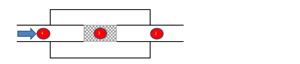
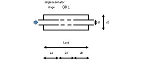
Figure 2 details characteristic lengths of element 3 (perforated tube) of a reactive silencer according to the EC1P1 mounting referenced in the SILDIS® software; La (m) and Lb (m) are the lengths of the non-perforated sections (upstream and downstream, respectively), and Lc (m) is the length of the perforated section. Overall length of the chamber is L = La + Lc + Lb (m).
|
Figure 2 Characteristic lengths of element 3 (perforated tube) of a reactive silencer (muffler) for the EC1P1 mounting referenced in the SILDIS® software (concentric tube resonator) |
The calculations involved are of practical interest, possibly in the context of engineering or Research and Development (R&D) projects, for the design of various noise-attenuating devices:
- for internal combustion engine exhaust systems
Input data (to be entered in Excel worksheets of SILDIS® software Module 1) in case of a silencer (muffler) with a perforated tube
The input data required for the computation are listed hereafter in reference with the above data (see figures in brackets in the previous §, used as placemarks for explaining the selection below). The input cells are referred to thanks to their Excel’s coordinates (column / line) in the following part extracted from user’s manual.
Worksheet [in COALA]
| Item | Cell for input | Foreseen action | Input | See placemark / comment |
| Language | Z1 | For english, select E, for french select F | E | [21] |
| Temperature (°C) | D7 | Enter a real number | 30 | [11] |
| Pressure (Pa) | D8 | Enter a positive real number | 100000 | [12] |
| Dry clean air ? (0/1) | D10 | For "yes", enter 1; for "no", enter 0 | 1 | [9] |
| Lw0 (dB ref. 1pW) | C15 to L15 | Enter a positive real number for the sound power level per 1/1 octave frequency band | 130 | [13] |
Worksheet [in COSIL-1B] COmputation of SILencers
| Item | Cell for input | Foreseen action | Input | See placemark / comment |
| Mass flow rate (kg/s) | B5 | Enter a positive real number | 0.08 | [10] |
| Inlet diameter (m) | B7 | Enter a positive real number | 0.05 | [3] |
| General model of flow acoustic power | S5 | Select a model (in a list) | 3733c* | [15] |
| Model of thermodynamic correction | S6 | Select a model (in a list) | 3733c | [16] |
| Model of spectral correction | S7 | Select a model (in a list) | 3733c | [17] |
| Mounting | B19 | Select a model (in a list) | EC1 | [2] |
| Chamber model (stage 1) | AC19 | Select a model (in a list) | REA | [1] |
| Model for total pressure loss | AT61 | Select a model (in a list) | MUN1 | [14] |
| dS (stage 1) (m) | O88 | Enter a positive real number | 0.05 | [3] sélection par défaut |
| dL (stage 1) (m) | O89 | Enter a positive real number | 0.15 | [4] |
| Chamber total length L (m) | O93 | Enter a positive real number | 0.401 | [5] |
| Tube's thickness e (m) | M94 | Enter a positive real number | 0.002 | [22] |
| Tube's roughness Δ (m) | M95 | Enter a positive real number | 0.00015 | [18] |
| Moddel for tuning | AF101 | Select a model (in a list) | MUN1 | [27] |
| Geometric length | AE105, AG105 | Enter a positive real number | 0.18505, 0.084 | [6] [7] |
| Tube's thickness e (m) | AE106 | Enter a positive real number | 0.002 | [22] |
| Geometric length Lx ≠ 0 (m) | H137, J137 | Enter a positive real number | 0.18505, 0.084 | [6] cf. cell AE105, [7] cf. cell AG105 |
| Model for total pressure loss | H141, I141 | Select a model (in a list) | IDE2, IDE2 | [14] default selection |
| Model for added length | AG250, AI250 | Select a model (in a list) | MUN1 | [19] |
Worksheet [in ⓒ 1]
| Item | Cell for input | Foreseen action | Input | See placemark / comment |
| Diameter of the holes | H5 | Enter a positive real number | 0.003 | [23] |
| Perforation ratio | H6 | Enter a positive real number | 0.196 | [24] |
| Impedance model | H8 | Select a model (in a list) | MUN | [25] |
| Rear added length model | H9 | Select a model (in a list) | CO-CUM | [26] |
| Front added length model | H10 | Select a model (in a list) | CO-CUM | [26] |
Worksheet [in-out CODIS-1B] COmputation DISplay
| Item | Cell for input | Foreseen action | Input | See placemark / comment |
| Model pour ΔL | AN48 | Select a model (in a list) for acoustic performance without flow noise indicator | TL | [20] |
Sizing results for a silencer (muffler) with a perforated tube with Module 1B of software SILDIS®
Results: main performance parameters for the silencer (muffler) with a perforated tube
Sound power level with silencer, after consideration of regeneration noise that limits sound attenuation: not defined in terms of overall value expressed in dB(A)
Silencer sound transmission loss: not defined in terms of overall value expressed in dB(A)
Total silencer pressure loss: 90 Pa
In the present case, the results in terms of sound power level with the silencer and in terms of sound transmission loss - usually expressed, concerning simulation with SILDIS® software, as overall A-weighted values for frequency range 20 Hz - 20 Hz - are not available not only due to the necessary consideration, for the evaluation of such overall values, of high-frequency performance characteristics whereas, since the calculations rely on the plane-wave assumption, the agreement between simulation and measurement results is best (indeed, excellent) for circular geometry up to frequency f1,0 = 1.84 * c / (π.d) * √ (1- M²) (Hz), but less good around frequency f2,0 = 3.05 * c / (π.d) * √ (1- M²) (Hz) and even less good for frequency f0,1 = 3.83 * c / (π.d) * √ (1- M²) (Hz), formulas in which f1,0, f2,0, and f0,1 correspond to the first higher-order modes, with d: diameter, c: speed of sound, and M: Mach number for silencer operating conditions.
The fundamentals of modeling of the physical phenomena involved - specifically regarding sound propagation in systems using perforated elements (such as concentric-tube resonators) - require calculations involving 4x4 matrices (with complex terms), for which different operations are required e.g. matrix inversion, eigenvector and eigenvalue calculation, and the solving of transcendental polynomial equations of the fourth degree with complex unknowns. With one exception, the challenges associated with using Excel for these calculations have been overcome - albeit with considerable difficulty for some steps - to successfully obtain the expected simulation results:
- using the only known analytical method capable of achieving this
- of which comparison with bibliographic data (finite element method - FEM - simulations and measurements), proves to be consistently safisfactory within the validity limits of the underlying assumptions i.e. in the absence of higher-order mode effects for very high frequency
The exception - and his is the cause for the inability to display overall values for usual performance indicators mentioned abobe - relates to a specific, currently unresolved issue regarding the elimination of duplicate results when solving for the roots of 4th-degree polynomial transcendental equations with complex unknowns in the ultra-high-frequency range; in this instance, calculations (given the selected input data and settings) are possible only up to 7246 Hz - a frequency however well above that of the first higher-order modes - which should not pose any practical problem.
Results: display of worksheet [in-out CODIS1B] (COmputation of DISplay) of Module 1B of software SILDIS® for the silencer (muffler) with a perforated tube
Acoustics & Aerodynamics/aeraulics
In what follows, performance indicators are linked by the formulas Lw1 = 10 * log [10^ (0.1 * (Lw0 – ΔLi’)) + 10^ (0.1 * Lw)] ; ΔL = Lw1 - Lw0
|
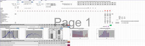
Figure 3 Result of the acoustic and aeraulic/aerodynamic sizing of a reactive silencer with expansion chamber with an optimized (tuned) perforated tube, using SILDIS® software. |
Results: screenshots of worksheet [out EC1P1] of Module 1B of software SILDIS® in case of a silencer (muffler) with a perforated tube for the silencer (muffler) with a perforated tube
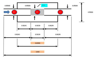
The displayed dimensions are the result of the entered data, allowing for verification of the input data's suitability (with the software, other sketches are available showing added lengths and total lengths - including added lengths - that are taken into account).
|
Figure 4 Summary of dimensions entered for modeling the reactive silencer with an optimized (by tuning) expansion chamber with a perforated tube using SILDIS® software. |
Remarks regarding the performance of a reactive silencer (muffler) with a simple expansion chamber with a perforated tube simulated with Module 1B of software SILDIS®
The input and output data (simulation results) above are those of the version of Module 1B of the SILDIS® software normally sold; some cells (e.g. model selections for different calculation steps) are pre-filled by default with robust selections (which can be modified by the user) for the considered silencer mounting. In order to limit questions from possibly inexperienced users in relation to the input data to be considered (explanations being provided in user's manual foreseen to be completed by a training), it is possible to restrict the functionalities of the software package by fixing (instead of allowing them to vary) some input data/some models for different steps of the calculations (depending on applications), so as to further simplify the use.
The Module 1 of software SILDIS® allows reactive silencer (muffler) with a simple expansion chamber with perforated tube simuled performance results:
- not necessarily using english language: french is possible too (also for entering input data)
- possibly comparable with some laboratory measurement standards e.g. NF EN ISO 7235 Acoustics - Laboratory measurement procedures for ducted silencers and air terminal units- Insertion loss, flow noise and total pressure loss (when appropriate models are selected in software drop-down menus)
- which can be obtained in less than a quarter of an hour, including time necessary for data entry (cf. tutorial of which link is provided in present post bottom, covering the case of a simple expansion chamber and involving a very similar timeframe for obtaining results[0])
Acoustic performance - without the consideration of self-noise - is determined using the transfer matrix method to model sound transmission with fluid flow through a cascade of basic silencer elements, the arrangement of which (i.e. their specific sequence) is pre-programmed for various configurations (depending on element to be considered for the modeling, to which corresponds a matrix relevant for its group[1], for which the - geometric - characteristic length is adjusted by a length correction[2] that accounts for the specific geometry. Consequently, the modeling approach is not limited to the case of the simple expansion chamber with a perforated tube as considered in this example.
The Module 1B of the SILDIS® software also enables the prediction of silencer performance for other cases - such as those encountered in various industrial applications - involving modeling based on various configurations (more or less usual)[3] for which the necessary calculations are fully programmed:
- involving up to 3 expansion chambers in series:
- possibly purely reactive (possibly accounting for gas flow direction reversal(s), e.g. using overlapping connecting tubes)
- possibly including a dissipative chamber[4]
- possibly including 1 or 2 Helmholtz resonators (with short or long neck)
- possibly featuring a radial silencer inlet
- possibly featuring a radial silencer outlet
With Module 1B of the SILDIS® software, acoustic performance excluding self-noise (this later being calculated separetely with the same software module) can be evaluated using various indicators:
- sound transmission loss (TL) (as in this example)
- insertion loss (involving source and load impedances)
- sound pressure level difference at specified locations (sometimes referred to as "noise reduction")
These acoustical performance indicators are evaluated using an analytical method, whereas the evaluation of other reactive silencers (mufflers) with a simple expansion chamber and perforated tube(s) performance indicators is based on regressions.
Overview of the methodology used for the evaluation of acoustic & aerodynamic performance indicators of reactive silencers with siingle expansion chamber with perforated tube(s) with Module 1B of software SILDIS®
| Performance indicator | Performance without flow noise ΔL' | Flow noise Lw | Total pressure loss Δpt |
| Methodology | Analytic | Regression based on measurements | Regression based on measurements |
Thus, Module 1B of the SILDIS® software enables using a single Excel workbook[4] and a single data entry step, while employing different models depending on the element group[1] the calculation of the aerodynamic and acoustic performance of reactive silencers with perforated tube(s), this latter including the influence of self-generated noise (due to flow).
The software feature allowing for the tuning of such concentric resonators via extended inlet and outlet tubes (unperforated tube sections La & Lb on either side of the perforated section with length Lc) enables the maximization of acoustic performance. It should be noted that the recommended values for the geometric lengths upstream and downstream (La & Lb) of the perforated section - provided by the software - are not necessarily perfectly exact values for eliminating frequency response dips in the acoustic filter curve (as they are influenced by the acoustic impedance of the perforated tube, depending on the chosen model); however they are very good approximations and at the very last they can serve as starters for a potential supplementary trial-and-error refinement (typically within a range of a few millimeters), a step not undertaken in the context of this case study (as not indispensable).
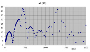
The figure below illustrates the following key results regarding sound transmission loss:
- it is not near-zero near frequencies that are multiples of c/2L = 435 Hz, as would be the case for a simple expansion chamber (referred to as EC1 in SILDIS® software library) without tuning (for the tuned EC1P1 configuration: it remains above 10 dB)
- it is significantly higher than that of a simple, untuned expansion chamber EC1 (for the latter: 13.2 dB as a maximum[5]) across a wide frequency range
For the mounting EC1P1, the first dip with near-zero performance in the noise attenuation curve appears at the frequency 2c/L = 1742 Hz i.e. above the frequency f1,0 = 1364 Hz limiting the plane waves propagation frequency domain; a reactive silencer dimensioned in this way (following the tuning rules encoded in the SILDIS® software) offers performance of great practical value e.g. when dealing with noise sources that have peak sound emissions within the frequency ranges where the resulting acoustic filter performs best.
|
Figure 5 Acoustic performance of a reactive silencer with a perforated tube using SILDIS® software (concentric tube resonator): sound transmission loss with tuning via extended tubes (as displayed on the CODIS-1B in-out worksheet: cf. screenshot above) |
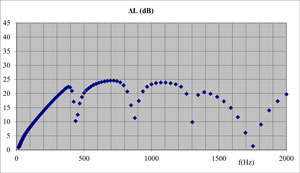
As with a simple expansion chamber, the phenomenon responsible for eliminating - when tuned correctly - three-quarters of the dips in the frequency response curve of the EC1P1 acoustic filter assembly is the resonance of the cavities (with an impervious rigid end) created by the tubes extending into the chamber's inlet and outlet, with performance peaks at frequencies that would otherwise correspond to dips.
Modeling of reactive silencers with two perforated tubes using Module 1B of the SILDIS® software (plug mufflers i.e. a transverse closure)
Perforated tubes are components frequently incorporated into the design of reactive silencers (mufflers). Using a single perforated tube (EC1P1 configuration, corresponding to a simple resonator) is not the only option available for acoustic and aerodynamic simulation in this regard. Module 1B of the SILDIS® software also allows for the modeling of a reactive silencer featuring two perforated tubes (therefore it comes to a double resonator), each forming a sub-stage of a single expansion chamber (EC1P2 configuration), sometimes referred to as a "plug-type silencer" due to the presence of a transverse partition (or plug) that forces the fluid to flow:
- first through the orifices (drillings) of the first perforated tube tube (from the inside towards outside)
- then (over a total length determined by the axial dimension of the "plug") through the annular section (the space between the outer surface of the perforated tube and the inner wall of the silencer's expansion chamber casing)
- finally, through the orifices (drillings) of the second perforated tube (from outside towards inside)
The dimensional characteristics of the two perforated tubes can differ (e.g regarding the size and number of drillings), further expanding the possibilities for fine-tuning noise attenuators to achieve performance levels - which remain equally easy to predict - that closely match specific requirements depending on the context (here again, SILDIS® software enables quick and easy tuning of such a reactive silencer by adjusting the lengths of the unperforated tube sections), potentially offering a different compromise between acoustic and aerodynamic performance.
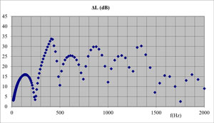
The figures below (numbered 6 to 9) relate to the EC1P2 setup, featuring two perforated tubes identical to the one envisaged for the EC1P1 setup (depending on the chosen arrangement: with a short or long annular section).
|
Figure 6 Sketch of a reactive silencer with two perforated tubes (plug-type silencer i.e. with transverse partition between 2 perforated tubes) that can be modeled using SILDIS® software |
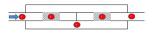
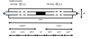
Figure 7 details the characteristic lengths of the elements of a reactive silencer according to the EC1P2 mounting referenced in the SILDIS® software (plug muffler i.e. with transverse partition between 2 perforated tubes):
- element 5: La1-2 (m) and Lb1-2 (m) are the lengths of the non-perforated sections (upstream and downstream, respectively), and Lc1-2 (m) is the length of the perforated section. The total length of the sub-stage is Lacb1-2 = La1-2 + Lc1-2 + Lb1-2 (m)
- element 3: Lb1-1 (m) and La1-1 (m) are the lengths of the non-perforated sections (upstream and downstream, respectively), and Lc1-1 (m) is the length of the perforated section. The total length of the sub-stage is Lbca1-1 = Lb1-1 + Lc1-1 + La1-1 (m)
- element 4: Ld is the length of the plug (i.e. of the transverse partition between perforated tubes). The total length of the chamber is Ltot = Lacb1-2 + Ld + Lbca1-1 (m)
|
Figure 7 Characteristic lengths of the elements of a reactive silencer for the EC1P2 mounting referenced in the SILDIS® software (plug-type muffler i.e. with transverse partition between 2 perforated tubes) |
|
Figure 8 Sound transmission loss of a reactive silencer with 2 perforated tubes: plug muffler (calculation results with software SILDIS®): when Lb1-1 = Lb1-2 & La1-1 = La1-2 (short annular section) |
|
Figure 9 Sound transmission loss of a reactive silencer with 2 perforated tubes: plug muffler (calculation results with software SILDIS®) when Lb1-1 = La1-2 & La1-1 = Lb1-2 (long annular section) |
Overall, regarding reactive silencers (mufflers) with perforated tube(s) sizing
The combination of its features makes the SILDIS® software package - at the very least - a rarity, especially when the simulation capabilities it offers are accompanied by numerous other strengths:
- Module 1 of the SILDIS® software eliminates the often tedious (complex, delicate, time-consuming, and costly) tasks associated with other calculation methods, thus offering several advantages (related to the fact that its use consists exclusively of filling in Excel spreadsheet cells with numerical values and/or selecting models from drop-down menus):
- no specific prerequisites for the user
- no need for extensive training, as getting started is easy after a very quick initial support session
- no need to import or create the silencer geometry, as it is simply configured by selecting dimensions
- no need for meshing
- the calculation time is not counted in hours, or even minutes
- the basic investment is limited to a single (multi-user) license with initial onboarding support for getting started (advanced support is available as an option), at no additional cost for subsequent years
- the license cost is such that even occasional use is sufficient to recoup, all the more so when it comes to a software package providing - notably for parametric studies - silencer performance evaluations that would be more expensive to obtain otherwise (assuming they are then as complete and reliable ?)
The Module 1B of software SILDIS® (based on Excel) is the outcome of decades of development and validation (in conditions meeting requirement of ISO 9001 relating to quality management systems) in the domain of acoustics (with a specialization in sound propagation and transmission in ducts and multilayer structures) and aeraulics by a human ressource able to combine theoretical considerations with field technical feedback (laboratories, measurements sites). It is a polyvalent, user friendly and reliable tool for sizing reactive silencer (possibly with the integration of a dissipative stage[4]) in all contexts: from easiests cases (ventilation/air handling systems with ambiant thermodynamic conditions) up to most demanding applications in industry e.g. in energy production sector or for test benches (customizations are possible for a tailor-made tool, even for non specialized users).
Programming, marketing, training & hotline are available from one company: Isolation Technologie Services aka ITS. Being available with a near-perpetual licence (100 years), Module 1 of software SILDIS® is a must-have for anyone involved in acoustical insulation/noise control, for engineering studies as well as for Research & Development (e.g. silencer manufacturers or integrators, engineering companies, acoustic consultants & architects offices).
[0] cf. https://www.its-acoustique.fr/en/computation-reactive-silencer-simple-expansion-chamber-sildis-software-excel and cf. tutorial below
[1] in the particular case of reactive silencers with perforated tube(s): Uniform Tubes (UT), Perforated Tubes (PT) for concentric resonators and plug mufflers; for other mountings (in addition): Extended Tubes (ET), Side Tubes (ST), Transverse Tubes (TT), Variable Tubes (VT), dissipative section (DIS), Helmholtz resonators (HR)
[2] regressions combining teh geometrical parameters of each perforated tube
[3] Reactive silencers mountings for which computation is possible with software SILDIS®: cf. link
[4] accounting for a dissipative stage requires a preliminary calculation using Module 1 of the SILDIS® software, with some output data (the real and imaginary parts of the complex wavenumber in the airway) serving as input data for Module 1B
[5] based on formula TLmax = 10LOG10(1+0.25(m-1/m)2) with m: expansion ratio i.e. m = (d2/d1)2