The SILDIS software (Excel) enables the modeling of acoustic & aerodynamic performance of a reactive silencer/muffler with a chamber with radial i.e. lateral aka side inlet & outlet as illustrated by an example (numbered 1B.4.6 in the User's manual). Like a standard simple expansion chamber, this type of noise-reduction equipment:
- contains no porous sound-absorbing materials
- derives its effectiveness from the reflection of sound waves at points where the cross-sectional area changes (e.g. sudden expansions or contractions) and/or from the presence of a rigid end wall that causes a reversal in the gas flow (a resonator effect)
The fact that the silencer’s inlet and outlet are radial (i.e. positioned on the sides) forces the gas flow to change direction twice; this contributes significantly to the device's acoustic performance: as is always the case with such sound-attenuation equipment, varying depending on frequency and, naturally, the operating conditions (such as the nature, temperature, pressure, and flow rate of the gas in question).
Problem statement (envisaged application relating to the computation of a reactive silencer/muffler with a simple expansion chamber with radial (i.e. side) inlet/outlet using software SILDIS)
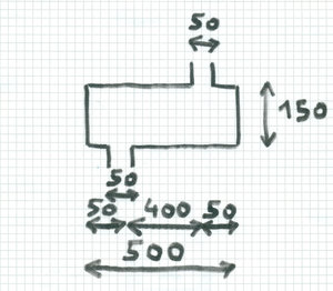
The objective is to calculate the acoustic and aerodynamic performance of a purely reactive silencer/muffler [1] featuring an expansion chamber with radial (i.e. lateral aka side) inlet and outlet ports, such a mounting being referred to as "EC1SISO" in the software [2], with a circular cross-section, with an inlet and outlet diameter of dS = 50 mm [3], an expansion chamber diameter of dL = 150 mm [4], and a length of L = 500 mm [5], the axis of the inlet tube is positioned at a distance of 50 mm from the end of the silencer (on the inlet side) [6], and the axis of the outlet tube is positioned at a distance of 50 mm from the end of the silencer (on the outlet side) [7]; the lengths of the tubes extending outside the expansion chamber are considered negligible i.e. they are taken to be zero [8]. The silencer is intended for use with a fluid close to clean, dry air [9], with a flow rate of 0.01 kg/s [10] at 19.65°C [11] and a pressure of 101250 Pa [12]. The reference spectrum is assumed to be "pink noise" with a sound power level of 130 dB/octave [13]. Total pressure loss is calculated using the IDE2 model for uniform tubes [14]. Silencer self-noise is calculated according to the general 3733c* model [15], the 3733c thermodynamic correction model [16], and the 3733c spectral correction model [17]. Tube roughness is set to 0.00015 m [18]. The TCC1 added-length model is used [19]. Transmission loss ("TL") is the chosen indicator of acoustic performance (excluding self-noise) [20]. The language used is English [21].
|
Figure 1 Sketch (hand-drawn) of a simple expansion chamber with radial inlet and outlet for the calculation example using the SILDIS software under consideration (dimensions in mm) |
|
Figure 2 Sketch of a reactive silencer/muffler with a single expansion chamber with radial inlet and outlet (EC1SISO) as modeled using SILDIS software; element 6 is the uniform inlet tube (with the smallest diameter), element 5 is an extended inlet, element 4 is a uniform tube (with the largest diameter), element 3 is an extended outlet, and element 2 is the uniform outlet tube (with the smallest diameter) |
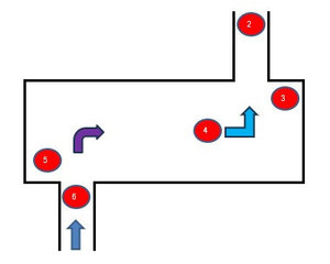
Input data for the computation of a reactive silencer/muffler with a simple expansion chamber with radial (i.e. side) inlet/outlet (to be entered in Excel worksheets of SILDIS software Module 1)
The input data required for the computation are listed hereafter in reference with the above data (see figures in brackets in the previous §, used as placemarks for explaining the selection below). The input cells are referred to thanks to their Excel’s coordinates (column / line) in the following part extracted from user’s manual.
Worksheet [in COALA]
| Item | Cell for input | Foreseen action | Input | See placemark / comment |
| Language | Z1 | For english, select E, for french select F | E | [21] |
| Temperature (°C) | D7 | Enter a real number | 19.65 | [11] |
| Pressure (Pa) | D8 | Enter a positive real number | 100750 | [12] |
| Dry and clean air ? (0/1) | D10 | For "yes" enter 1; for "no"; enter 0 | 1 | [9] |
| Lw0 (dB ref. 1pW) | C15 to L15 | Enter a positive real number for the sound power level per 1/1 octave frequency band | 130 | [13] |
Worksheet [in COSIL-1B] COmputation of SILencers
| Item | Cell for input | Foreseen action | Input | See placemark / comment |
| Mass flow rate (kg/s) | B5 | Enter a positive real number | 0.01 | [10] |
| Inlet diameter (m) | B7 | Enter a positive real number | 0.05 | [3] |
| General model of flow acoustic power | S5 | Select a model (in a list) | 3733c* | [15] |
| Model of thermodynamic correction | S6 | Select a model (in a list) | 3733c | [16] |
| Model of spectral correction | S7 | Select a model (in a list) | 3733c | [17] |
| Mounting | B19 | Select a model (in a list) | EC1SISO | [2] |
| Chamber model (stage 1) | AC19 | Select a model (in a list) | REA | [1] |
| dS (stage 1) (m) | O88 | Enter a positive real number | 0.05 | [3] selection by default |
| dL (stage 1) (m) | O89 | Enter a positive real number | 0.15 | [4] |
| Chamber total length L (m) | O93 | Enter a positive real number | 0.5 | [5] |
| Tube's roughness Δ (m) | M95 | Enter a positive real number | 0.00015 | [18] |
| Geometric length Lx ≠ 0 (m) | H137, J137, Y137, Z137 | Enter a positive real number | 1E-10, 1E-10, 0.05, 0.05 | [5], [6], [7], [8] |
| Model for total pressure loss | H141, I141, J141 | Select a model (in a list) | IDE2, IDE2, IDE2 | [14] selection by default |
| Model for added length | K250, N250 | Select a model (in a list) | TOF1, TOF1 | [19] |
Worksheet [in-out CODIS-1B] COmputation DISplay
| Item | Cell for input | Foreseen action | Input | See placemark / comment |
| Model pour ΔL | AN48 | Select a model (in a list) for acoustic performance without flow noise indicator | TL | [20] |
Performance simulation results of a reactive silencer/muffler with a simple expansion chamber with radial (i.e. side) inlet/outlet with Module 1B of software SILDIS
Results: main performance indicators for a reactive silencer (muffler) with a simple expansion chamber with a side outlet
Upon completion of the modeling and simulations, and after all calculations, various performance indicators are obtained for the silencer.
Sound power level with silencer (muffler) 126.0 dB(A), after consideration of regenerated noise which limits sound attenuation
Silencer (muffler) sound transmission loss 11.1 dB(A)
Silencer (muffler) total pressure loss 14 Pa
In the present case, the results obtained in terms of sound power level with the silencer (muffler) and in terms of sound transmission loss - expressed as overall A-weighted values - are not accurate due to the consideration, for the evaluation of such overall values, of high-frequency performance characteristics - as required - , while the calculations rely on the plane-wave assumption, the agreement between simulation and measurement results - in case of a circular geometry - is optimal (indeed, excellent) up to frequency f1.0 = 1.84 * c / (π.d) * √ (1- M²) (Hz), but less good around frequency f2.0 = 3.05 * c / (π.d) * √ (1- M²) (Hz), and even less good for frequency f0.1 = 3.83 * c / (π.d) * √ (1- M²) (Hz), formulas in which f1,0 , f2,0 , f01 correspond to the first higher-order modes (where d = diameter, c = speed of sound, and M = Mach number under operating conditions).
In this regard, it should be noted that significant high-frequency performance is generally not expected from a reactive silencer stage, being rather assigned to a dissipative silencer stage, with which it can generally be quite easily obtained.
Results: screenshots of worksheet [in-out CODIS1B] (COmputation of DISplay) of Module 1B of software SILDIS for a reactive silencer/muffler with a simple expansion chamber with radial (i.e. side) inlet/outlet
Acoustics & Aerodynamics/aeraulics
In what follows, performance indicators are linked by the formulas Lw1 = 10 * log [10^ (0.1 * (Lw0 – ΔLi’)) + 10^ (0.1 * Lw)] ; ΔL = Lw1 - Lw0
|
Figure 3 Results of acoustic & aerodynamic modeling of a reactive silencer with SILDIS software: simple expansion chamber with radial inlet and outlet |
Results: screenshots of worksheet [out EC1SO] of Module 1B of software SILDIS for a reactive silencer/muffler with a simple expansion chamber with radial (i.e. side) inlet/outlet
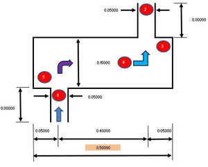
The displayed dimensions are the result of the entered data, allowing for verification of the input data's suitability (with the software, other sketches are available showing added lengths and total lengths - including added lengths - that are taken into account).
|
Figure 4 Reactive silencer: simple expansion chamber with radial inlet and outlet (dimensions used for a sample calculation with the SILDIS software) |
Remarks regarding the performance of a reactive silencer/muffler with a simple expansion chamber with radial (i.e. side) inlet/outlet simulated with Module 1B of software SILDIS
The input and output data (simulation results) above are those of the version of Module 1B of the SILDIS software normally sold; some cells (e.g. model selections for different calculation steps) are pre-filled by default with robust selections (which can be modified by the user) for the considered silencer mounting. In order to limit questions from possibly inexperienced users in relation to the input data to be considered (explanations being provided in user's manual foreseen to be completed by a training), it is possible to restrict the functionalities of the software package by fixing (instead of allowing them to vary) some input data/some models for different steps of the calculations (depending on applications), so as to further simplify the use.
The Module 1B of software SILDIS allows reactive silencer with a simple expansion chamber with a side outlet simuled performance results:
- not necessarily using english language: french is possible too (also for entering input data)
- possibly comparable with some laboratory measurement standards e.g. NF EN ISO 7235 Acoustics - Laboratory measurement procedures for ducted silencers and air terminal units- Insertion loss, flow noise and total pressure loss (when appropriate models are selected in software drop-down menus)
- which can be obtained in less than a quarter of an hour, including time necessary for data entry (cf. tutorial[0])
Acoustic performance - without the consideration of self-noise - is determined using the transfer matrix method to model sound transmission with fluid flow through a cascade of basic silencer elements, the arrangement of which (i.e. their specific sequence) is pre-programmed for various configurations (depending on element to be considered for the modeling, to which corresponds a matrix relevant for its group[1], for which the - geometric - characteristic length is adjusted by a length correction[2] that accounts for the specific geometry. Consequently, the modeling approach is not limited to the case of the simple expansion chamber as considered in this example.
The Module 1B of the SILDIS software also enables the prediction of silencer performance for more complex case studies - such as those encountered in certain industrial applications - involving modeling based on various configurations (more or less usual)[3] for which the necessary calculations are fully programmed:
- involving up to 3 expansion chambers in series:
- possibly purely reactive, as in the example featured in this publication (possibly accounting for gas flow direction reversal(s), e.g. using overlapping connecting tubes)
- possibly including a dissipative chamber[4]
- possibly including 1 or 2 Helmholtz resonators (with short or long neck)
- possibly including 1 or 2 concentric resonators - with perforated tube(s) -
- possibly featuring a radial silencer inlet
- possibly featuring a radial silencer outlet
With Module 1B of the SILDIS software, acoustic performance excluding self-noise (this later being calculated separetely with the same software module) can be evaluated using various indicators:
- sound transmission loss (TL) (as in this example)
- insertion loss (involving source and load impedances)
- sound pressure level difference at specified locations (sometimes referred to as "noise reduction")
These acoustical performance indicators are evaluated using an analytical method, whereas the evaluation of other reactive silencers (mufflers) performance indicators is based on regressions.
Overview of the methodology used for the evaluation of acoustic & aerodynamic performance indicators of reactive silencers (muffler) with Module 1B of software SILDIS
| Performance indicator | Performance without flow noise ΔL' | Flow noise Lw | Total pressure loss Δpt |
| Methodology | Analytic | Regression based on measurements | Regression based on measurements |
Returning to reactive silencers (muffler) with expansion chamber(s) with a side outlet, as modeled in this calculation example, there are numerous applications in the power generation sector (compressors, internal combustion engines for propulsion or electricity generation, i.e. generator sets) and for test benches:
- regarding workers protection (employees and external contractors handling supervision and maintenance, as well as engineers and technicians conducting laboratory tests who must be protected from hearing damage)
- regarding environmental protection (ensuring peace and quiet for neighbors of facilities housing engines, pumps, other turbomachinery, or other process equipment)
Thus, Module 1B of the SILDIS software enables the calculation of the aerodynamic and acoustic performance of reactive silencers - including self-generated noise (due to flow) - using a single Excel workbook[4] and a single data entry step, while employing different models depending on the element group[1].
Returning to the calculation example that is the subject of this article, the acoustic performance shown above was obtained by using the dimensions listed in the problem statement above for the lengths along the longitudinal axis of the expansion chamber (what could be more normal ?). It should be kept in mind that these dimensions do not necessarily represent an optimum, in terms of combined selection (especially if they have not been specifically determined by someone having the ppropriate know-how). Even without specialized knowledge regarding the calculations for reactive silencers - which are far from trivial - a user of the software can investigate this further; the software provides an option to optimize acoustic performance through "tuning" i.e. by using - for some of the elements of the assembly - lengths (computed a special feature) that can be entered by the user for a better silencer's efficiency, as illustrated in Figure 5:
- for the configuration "without" tuning:
- the sound transmission loss curve exhibits dramatic dips near multiples of 336.5 Hz; such performance weaknesses can pose problems when attempting to reduce noise emissions from certain noise sources (in practice, the peak in efficiency observable in the vicinity of the 1696 Hz frequency does not necessarily correspond to any need having prompted the use of a reactive silencer, of which one expects - in general - a noise reduction for low frequencies)
- for the configuration "with" tuning, where the distance from the inlet (resp. outlet) tube axis to the inlet-side (resp. outlet-side) end cap is no longer the original 50 mm, but rather the value calculated by the software to maximize silencer efficiency:
- such dips no longer appear near multiples of 336.5 Hz, and the transmission loss in this frequency range reaches a maximum that exceeds the peak achieved by the "untuned" configuration
- dips appear only near multiples of 1391 Hz i.e. near (specifically, above) the frequency f1,0 = 1340 Hz), and efficiency is superior to that of the configuration "witout" tuning across a wide frequency range - roughly between 100 Hz and 1100 Hz -; a reactive silencer/muffler with radial inlet and outlet sized in this way - based on the tuning rules programmed into the SILDIS software - offers highly practical performance, as it covers several adjacent octave bands within the 100 Hz – 1.1 kHz frequency range
|
Figure 5 Comparative acoustic performance of a reactive silencer with a simple expansion chamber with radial inlet and outlet using SILDIS software: sound transmission loss "with" and "without" tuning |
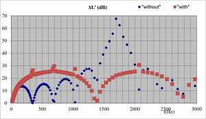
For the EC1SISO configuration, the phenomenon responsible for the disappearance - for the configuration "with" tuning - of three-quarters of the dips observed in the frequency response curve of the resulting acoustic filter is the resonance of the cavities with an impervious rigid back(which has a rigid, impermeable base) at both the inlet and the outlet of the expansion chamber; this results in performance peaks at frequencies that would otherwise correspond to dips.
Of course, it is also possible (why not?) to compare the acoustic performance of an expansion chamber with radial (i.e. lateral aka side) inlet and outlet ports (EC1SISO) against that of a standard, simple expansion chamber (EC1, where the inlet and outlet tubes are aligned), with all other parameters remaining equal; when sticking to data provided in the problem statement above, there is no extended length to consider inside the chamber: neither for the inlet nor for the outlet (which announces - for anyone knowing a bit the underlying physical phenomena) an efficiency curve with peaks and troughs that are closel spaced in terms of frequency. Figure 6 below presents the following results:
- for the configuration "without" radial inlet/outlet ports i.e. for the EC1 mounting:
- the sound transmission loss curve exhibits dramatic dips in the vicinity of frequencies that are multiples of c/2L = 343.2 Hz, where c is the speed of sound for the silencer’s operating conditions (in m/s) and L is the length of the expansion chamber (in m). Such performance weaknesses are, of course, problematic for the overall effectiveness of such a sound-attenuation device in practical applications
- the transmission loss reaches a maximum of 13.2 dB, a value that can also be calculated directly using the formula: TLmax = 10 * LOG10 [ 1 + 0.25 * (m - 1/m)² ], where m is the ratio of the respective cross-sectional areas of the chamber and the inlet/outlet tube
- for the configuration "with" radial (i.e. lateral) inlet/outlet ie.e for the EC1SISO mounting:
- such dips no longer occur in the vicinity of frequencies that are multiples of c/2L = 343.2 Hz, and the sound transmission loss is significantly higher than that of the configuration "without" radial inlet/outlet (the first dip in the noise-attenuation curve appears at a frequency of 2c/L = 1372.8 Hz i.e. in the vicinity of (and specifically above) the frequency f1,0 = 1340 Hz. A reactive silencer/mufler dimensioned in this way offers superior performance and is therefore of greater practical value
|
Figure 6 Comparative acoustic performance of a reactive silencer with a simple expansion chamber using SILDIS software: sound transmission loss "with" and "without" radial inlet/outlet |
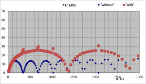
For the EC1SISO configuration, the phenomenon responsible for the disappearance of three-quarters of the dips observed in the acoustic filter's frequency response curve is (one more time) the resonance of cavities with rigid, impermeable ends: on the one hand at the inlet and on the other hand at the outlet of the expansion chamber, yielding performance peaks at frequencies that would otherwise correspond to dips.
In fact, the combination of such features makes the SILDIS software package - at the very least - a rarity, especially when the simulation capabilities it offers are accompanied by numerous other strengths:
- Module 1B of the SILDIS software eliminates the often tedious (complex, delicate, time-consuming, and costly) tasks associated with other calculation methods, thus offering several advantages (related to the fact that its use consists exclusively of filling in Excel spreadsheet cells with numerical values and/or selecting models from drop-down menus):
- no specific prerequisites for the user
- no need for extensive training, as getting started is easy after a very quick initial support session
- no need to import or create the silencer geometry, as it is simply configured by selecting dimensions
- no need for meshing
- the calculation time is not counted in hours, or even minutes
- the basic investment is limited to a single (multi-user) license with initial onboarding support for getting started (advanced support is available as an option), at no additional cost for subsequent years
- the license cost is such that even occasional use is sufficient to recoup, all the more so when it comes to a software package providing - notably for parametric studies - silencer performance evaluations that would be more expensive to obtain otherwise (assuming they are then as complete and reliable ?)
The Module 1B of software SILDIS (based on Excel) is the outcome of decades of development and validation (in conditions meeting requirement of ISO 9001 relating to quality management systems) in the domain of acoustics (with a specialization in sound propagation and transmission in ducts and multilayer structures) and aeraulics by a human ressource able to combine theoretical considerations with field technical feedback (laboratories, measurements sites). It is a polyvalent, user friendly and reliable tool for sizing reactive silencer (possibly with the integration of a dissipative stage[4]) in all contexts: from easiests cases (ventilation/air handling systems with ambiant thermodynamic conditions) up to most demanding applications in industry e.g. in energy production sector or for test benches (customizations are possible for a tailor-made tool, even for non specialized users).
Programming, marketing, training & hotline are available from one company: Isolation Technologie Services aka ITS. Being available with a near-perpetual licence (100 years), Module 1 of software SILDIS is a must-have for anyone involved in acoustical insulation/noise control, for engineering studies as well as for Research & Development (e.g. silencer manufacturers or integrators, engineering companies, acoustic consultants & architects offices).
[1] Uniform Tubes (UT), Extended Tubes (ET), Side Tubes (ST), Transverse Tubes (TT), Variable Tubes (VT), dissipative section (DIS), Helmholtz resonators (HR), Perforated Tubes (PT) for concentric resonators
[2] Termination Open Unflanged (TOU), Termination Open Flanged (TOF), Termination Connected-Coaxial, Termination Connected-Staggered (TCS), Termination Connected with Branch (TCB)
[3] Reactive silencers mountings for which computation is possible with software SILDIS: cf. link
[4] accounting for a dissipative stage requires a preliminary calculation using Module 1 of the SILDIS software, with some output data (the real and imaginary parts of the complex wavenumber in the airway) serving as input data for Module 1B.