Use of mufflers including perforated pipes to reduce gas flow noise
Mufflers including perforated pipes are used in different contexts for reducing gas flow noise (depending on the application: at ambient or variable temperature e.g. very high):
- compressed air networks (at suction and/or discharge)
- exhaust lines from thermal engines >depressurization vents (e.g. steam)
It is the passage of the gas flow through orifices (e.g. such as those resulting from drilling work on the longitudinal wall of a cylindrical duct, or - where appropriate - its transverse end) which is the basis of the sound attenuation, accompanied by a total pressure loss which must of course be maintained within limits compatible with the proper functioning of the considered process by judicious choices of geometric parameters, depending on the flow rate.
When inserted into a chamber, a perforated pipe constitutes a reactive stage of a silencer, which can be combined with other noise reduction stages:
- of the same nature (possibly: having a different geometry)
- of a different nature:
- reactive, when based on the presence of non-perforated tubes connecting volumes (e.g. Helmholtz resonators)
- dissipative, when there is a porous material absorbing sound
Design calculations of mufflers including perforated pipes for gas flow noise reduction
Design calculations for mufflers including perforated pipes for gas flow noise reduction are now possible using Module 1B of the SILDIS®[1] software, the features of which have been enhanced.
Although a fairly simple geometry can often be considered for the performance simulation of such devices, the calculations relating to muffler perforated pipes for gas flow noise reduction are - even in the case where only a single perforated pipe is considered, with perforations uniformly distributed over an area being the product of the considered circumference and length - notably more complicated than those relating to a number of other reactive elements (whose transfer matrix is of type 2*2), since the involved physical phenomena then require operations on matrices of type 4*4 as well as the determination of the roots of polynomials of degree 4 in the complex domain, for what concerns the evaluation of modal matrices to be carried out.
Indeed, the acoustic pressure and the particle velocity (and also associated parameter referred to as acoustical mass velocity), upstream and downstream of the perforated length of tube considered for such reactive stages, must be linked by a transfer matrix: both with regard to the cross section corresponding to the interior of the perforated tube, and also with regard to that corresponding to the exterior). Once this step of the modeling (which implies a sufficiently precise evaluation of the impedance of orifices not located in a plane, subject to both a grazing gas flow and a cross gas flow) has been carried out, the calculations can be contextualized (taking into account, where applicable, the resonant cavities created by any tubes upstream/and or downstream of the perforated length) for different configurations e.g. concentric tube resonator, expansion with cross flow, contraction with cross flow, constituting all new possible subassemblies of silencers (the number of such combinations being infinite), for which:
- acoustic performance can be calculated, by frequency band (1/21 octave, 1/3 octave, 1/1 octave) (dB):
- sound transmission loss (dB); it is the only indicator - among the three available as software output data - which does not depend on the impedance of the source i.e. upstream of the silencer (the existence of an anechoic termination is assumed downstream)
- insertion loss (dB)
- sound pressure level reduction (dB)
- aerodynamic performance can be calculated:
- total pressure loss (Pa)
For such sizings of silencers including perforated tubes for gas flow noise reduction, SILDIS®[1] software :
- constitutes an alternative to the use of tools - which ITS also has available[2] - by avoiding the sometimes tedious (and requiring specialized human resources) tasks of computer creation of geometry models and of meshes (often difficult for what concerns perforations, especially if they are distributed over the axial lines of a cylinder, numerous and small) and avoiding sometimes long calculation times, even with a powerful computer
- is based on analytical methods for studying the propagation of sound in ducts, with a cascade approach and, with programming in advance of the multiplications of the transfer matrices corresponding to more or less usual combinations of elements[3], for the best possible user-friendliness for the user (the creation of new combinations of elements are also possible “on demand” by an experienced human resource)
Examples of design calculations for mufflers including perforated tubes for gas flow noise reduction
Design calculations for mufflers with perforated pipes for gas flow noise reduction are possible with SILDIS® software. In addition to the thermodynamic conditions of the gas and its flow rate, the parameters that can be considered are purely geometric (diameter of the perforations, open area ratio, thickness and diameter of the tube and different lengths depending on the envisaged mounting - without forgetting, where applicable, the diameters of the chambers, similar to what is considered for other reactive silencer elements -).
- expansion chamber with 1 perforated pipe (EC1P1 mounting) also referred to as concentric tube resonator (cf. fig. 1a)
For an expansion chamber with 1 perforated pipe (EC1P1 mounting) also referred to as concentric tube resonator, a compartment with a circular cross section (i.e. a cylinder with a transverse partition at each end) is crossed longitudinally from side to side by 1 pipe - opening out - perforated over part of its length[4].
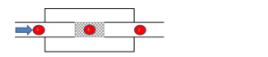
Figure 1a sketch of an expansion chamber with 1 perforated pipe (EC1P1 mounting) also referred to as concentric tube resonator (marks 2 & 4 designate uniform tubes, mark 3 designates a perforated tube/pipe)
Such a configuration is only distinguished from that of the EC1[3] mounting (simple expansion chamber, with extended inlet and/or outlet) - as far as construction is concerned - by the presence of the perforated tube.
For the EC1P1 mounting, in many cases, both acoustic and aerodynamic performance can be adjusted differently, possibly with:- better efficiency in noise reduction (e.g. higher transmission loss, and over a wider frequency range) ; among other things, the fairly characteristic dips generally observable on the sound transmission loss curve as a function of frequency, for the EC1 assembly (without perforated tube), at resonance frequencies which are depending on the length of the chamber and on the length of the extensions at the inlet and outlet can be reduced (as often desirable) by the addition of a perforated tube according to the principle of EC1P1 assembly, under the condition of a proper tuning (cf. fig. 1b)
- lower total pressure loss
When the length of the perforated zone is equal to the total length of the chamber, this configuration only differs from the C0[3][5] mounting (circular dissipative silencer without central splitter) - as far as the construction is concerned - only by the absence of sound-absorbing material, which eliminates the risk of its alteration (e.g. in the long term, during exposure to burning and chemically corrosive gases), and generally results in a lower manufacturing cost. A case study (taking into account all the input data, some of which have antagonistic impacts, and the more or less specific objectives of the considered project) is necessary to quantify the variation in performance of the EC1P2 assembly compared to the EC1P1 assembly or compared to other combinations of reactive or dissipative elements constituting silencers/mufflers to be inserted into a fluid network.
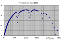
Figure 1b sound transmission loss of an expansion chamber with 1 perforated tube (EC1P1 assembly, according to the principle of figure 1a) of diameter 0.135 m, total length 0.400 m, with central tube of diameter 0.045 m, thickness 0.002 m, with drilling diameters of 0.003 m, a porosity of 20.0% ; the non-perforated length upstream of the perforated zone - the latter corresponding to 33.3% of the total length - is equal to 45.9% of the total length, the non-perforated length downstream of the perforated zone is equal to 20.8% of the length total. The fluid considered is air at a pressure of 101300 Pa, at a temperature of 300 degrees Celsius with a Mach number equal to 0.05 (the software also allows the calculation of the total pressure loss: 409 Pa for this simulation).
- expansion chamber with 2 perforated pipes (EC1P2 mounting) also referred to as plug muffler/silencer (cf. fig. 2a)
For an expansion chamber with 2 perforated pipe (EC1P2 mounting) also referred to as plug muffler/silencer, a compartment with a circular cross section (i.e. a cylinder with a transverse partition at each end) is crossed longitudinally from side to side by 2 pipes - opening out - each being perforated over part of its length[4] and with - between the two - a shutter preventing the direct passage of fluid (and sounds).
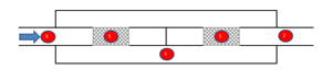
Figure 2a sketch of an expansion chamber with 2 perforated pipes (EC1P2 mounting) also referred to as plug muffler/silencer (marks 2, 4 & 6 designate uniform tubes, marks 3 & 5 designate perforated tubes/pipes)
Such a configuration is only distinguished from that of the EC1[3] mounting (simple expansion chamber, with extended inlet and/or outlet) - as far as construction is concerned - by the presence of the perforated tubes.
For the EC1P2 mounting, in many cases, both acoustic and aerodynamic performance can be adjusted differently, possibly with:- better efficiency in noise reduction (e.g. higher transmission loss, and over a wider frequency range)
- total pressure loss not necessarily higher or lower (depending on the combinaison of selected geometric parameters)
When the length of the perforated zone is equal to the total length of the chamber, this configuration only differs from the C0[3][5] mounting (circular dissipative silencer without central splitter) - as far as the construction is concerned - only by the absence of sound-absorbing material, which eliminates the risk of its alteration (e.g. in the long term, during exposure to burning and chemically corrosive gases), and generally results in a lower manufacturing cost.
In addition, compared to the EC1P1 assembly, the presence of an additional perforated tube allows variations in acoustic performance in particular linked to the involvement of a perforated tube impedance possibly different due to the geometric characteristics of the perforations (e.g. diameter, open area rate) and changes in other parameters e.g. the Mach number associated to the grazing gas flow and to thegas flow and through the orifices), and also notably linked to resonances of additional cavities at different frequencies due to the lengths involved ; particular vigilance is required with regard to maintaining at acceptable values the increase in the total pressure loss then induced.
A case study (taking into account all the data, some of which have antagonistic impacts, and the more or less specific objectives of the considered project ) is necessary to quantify the variation in performance of the EC1P2 assembly compared to the EC1P1 assembly (see fig. 2b) or compared to other combinations of reactive or dissipative elements constituting silencers to be inserted into a fluid network.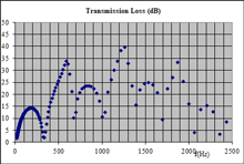
Figure 2b sound transmission loss of an expansion chamber with 2 perforated tubes (EC1P2 assembly, according to the principle of figure 2a) each of diameter 0.135 m, total length 0.400 m, with central tube of diameter 0.045 m, thickness 0.002 m, with drilling diameters of 0.003 m, a porosity of 20.0% ; the non-perforated length upstream of the perforated zone - the latter corresponding to 33.3% of the total length - is equal to 45.9% of the total length, the non-perforated length downstream of the perforated zone is equal to 20.8% of the length total ; the two perforated tubes are separated by a plug. The fluid considered is air at a pressure of 101300 Pa, at a temperature of 300 degrees Celsius with a Mach number equal to 0.05 (the software also allows the calculation of the total pressure loss: 409 Pa for this simulation).
- other uses of an expansion stage including a perforated pipe with cross-flow tube (ECF+ assembly) (cf. fig. 3)
For an expansion stage including a perforated pipe with cross-flow (ECF+ assembly), 1 perforated tube over part of its length[4] and provided at its end with a shutter preventing the direct passage of fluid (and sounds) is connected to a downstream circular section, of variable characteristics.
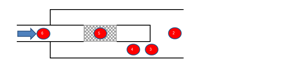
Figure 3 sketch of a comprehensive expansion stage with perforated tube (ECF+ assembly) (marks 2, 4 & 6 designate uniform tubes, mark 3 designates a sudden widening, mark 5 designates a perforated tube/pipe)
Such a configuration can be used alone (constituting a complete and self-sufficient sound attenuation device in some cases) or as an upstream part of various more sophisticated silencer assemblies, then combined with - downstream - other elements that can be modeled with the SILDIS®[ 1] software (reactive or dissipative) depending on the applications envisaged, thus offering extensive possibilities for adapting the acoustic and aerodynamic performance of mufflers & silencers for the reduction of gas flow noise, at ambient temperature as well as at (sometimes: very) high temperature.
Making it possible to predict the acoustic and aerodynamic performance of products and construction systems for soundproofing requiring sophisticated modeling with a tool that is simple and quick to use, reliable, precise and versatile is the objective of the Research and Development works in acoustics conducted by ITS.The design calculations for mufflers including perforated tubes for the reduction of gas flow noise can be carried out with the SILDIS® software either by the human resources of ITS (which developed and markets this simulation tool: the edition of software is an ITS activity assessed in compliance with the requirements of the ISO 9001 standard), or self-service (with subscription) in ASP[6] mode.
[1] Sound Impact Limitation Design for Industrialized Solutions (in Excel format)
[2] cf. Calculations in acoustics and computational fluid dynamics (FEM, BEM, CFD)
[3] cf. report PhR23_013
[4] the choice of the length of the perforated zone, like that of the length of the non-perforated zones located upstream and downstream, is - particularly with regard to the overall length of the chamber - determining for obtaining a performance without too much frequency irregularity
[5] cf. report PhR20_013_1
[6] ASP = Application Service Provider