ITS offers to perform calculations in acoustics and computational fluid dynamics (FEM [1], BEM [2], CFD [3]), in particular in the context of evaluating the performance of silencers (e.g. insertion loss, total pressure loss), namely when the geometry of the casing or of the internal parts of such soundproofing devices can not easily be taken into account with SILDIS® software modules relating to Limitation of noise transmission in ducts :
- for the dissipative section of silencers: in the case of absorbent linings of non-constant thickness, in the case of staggered splitters
- for the reactive section of silencers: in case of special geometries of internal parts (chambers or connecting tubes)
- whatever the physical phenomenon on which the efficiency of a silencer is based: for taking into account high order modes, and, in the case of circular geometry: for large cross sections, when the evaluation of Bessel and Neumann functions invlolves computation problems
Such situations may arise in the context of the design and sizing of noise attenuators for applications in the building sector (e.g. ventilation, air conditioning networks) or industrial (e.g. air intake and exhaust of combustion engines or turbines, pressurized gas venting).
In this regard, the services offered by ITS (assessed to meet the requirements of ISO 9001, like other engineering missions carried out by ITS) include all the steps of calculations in acoustics and computational fluid dynamics (FEM, BEM, CFD), as detailed below.
(Solid) geometric modeling of noise attenuators
The (solid) geometric modeling is the first step in acoustics and computational fluid dynamics (FEM, CFD) simulations of noise attenuators and is of particular importance, as it comes to the creation of a forms set able to reflect all physically relevant features of the problem, without the incombrance of minor details.
This necessiates the consideration of the dimensions of the various components of the silencer:
- casing (duct) e.g. with a rectangular, square or circular section, where appropriate : with changes in transverse dimension
- sound absorbing lining e.g. at the (possibly partial) periphery of the casing, or in the form of continuous (i.e. whose transverse dimension is equal to that of the duct) or discontinuous splitters (baffles) e.g. pod, staggered baffles
- aerodynamic profiles (upstream and/or downstream of sections with sound-absorbing materials) e.g. rectangular, pyramidal, or semi-circular
The human resource of ITS can create a 3D model (i.e. in 3 dimensions) taking into account the geometric characteristics influencing the performance indicators whose obtaining constitutes the object of the simulation and, with regard to the various existing surfaces, create groups to which properties and service conditions can be assigned at later stages of the calculation process.
In the case of soundproofing devices whose cross section presents a pattern, and with a view to limiting the resources (processors, memory) and the time of the steps for which they are involved, a simplified model may only take into account a limited number of identical sub-sets (sometimes: only one e.g. an absorbing spiltter among many others of the same constitution), under the condition that one can be satisfied with the exact non-consideration of some boundary conditions e.g. for what concerns symmetry planes.
In the case where it is desired that the results of the simulations can be compared with laboratory measurements (e.g. ISO 7235, ASTM E-477), the 3D model must take into account additional ductwork straight lengths sufficiently large upstream and downstream of the silencer (cf. fig. 1).
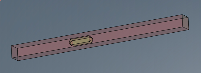
Fig. 1 perspective view - solid geometric modeling of a noise attenuator: central sound-absorbing splitter (with pyramidal ends) in a duct with consideration of straight lengths upstream and downstream
Definition of the fluid domain
The definition of the fluid model is the second step in acoustics and computational fluid dynamics (FEM, CFD) simulations, and it is not less crucial than the first.
It is a question, from the geometrical modelization (solid) of the silencer, to circumscribe and to specify, in an appropriate manner, the borders of the space (containing the fluid) in which the calculations will be carried out and to assign to the boundaries properties being predefined elsewhere e.g. for inlet and outlet, as well as for walls (i.e. casing and internal parts) (cf. fig. 2).

Fig. 2 longitudinal section - solid geometric modeling and representation of the fluid domain for the noise attenuator in fig. 1
Definition of a mesh
The definition of a mesh constitutes the third step of simulations in acoustics and computational fluid dynamics (FEM-BEM,CFD) and is capital with respect to the compromise which must be found, with regard to the level of discretization (i.e. the number, the geometry and the distribution of elementary cells), between on the one hand the expected precision of the simulation results (and also the speed to obtain the necessary convergence when solving the fluid dynamics or acoustics equations) and on the other hand the resources having to be committed to obtain them (increasing with the density of the mesh), a fortiori if one does not have the means of calculations worthy of those of a space agency, whereas one wishes computation times sufficiently short.
This is why it is so important to make the right choices in this area throughout the fluid domain:
- in the larger section and at the level of the constrictions: with elementary cells being sufficiently small when compared to the hydraulic diameter of the considered portion of the duct
- near the walls of the duct guiding the internal flow, and near obstacles (e.g. sound absorbing lining, possibly in the form of baffles or of central pod) with elementary cells proportionate to the thickness of the viscous boundary layer (laminar or turbulent, depending on the value of the Reynolds number)
Fig. 3 illustrates an example of a mesh in an aeraulic calculation context.
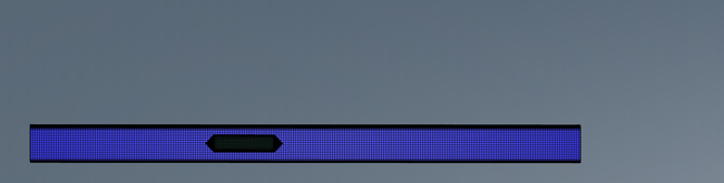
Fig. 3 longitudinal section - mesh for the fluid domain of fig.2
Other settings for simulations in acoustics and computational fluid dynamics
Other settings are necessary for simulations in acoustics and computational fluid dynamics (CFD) e.g. the definition of iteration numbers and convergence criteria, the management of processors for the calculations, the choice of a flow model, thermodynamic conditions, initial values of different physical quantities, the selection of a fluid and its modeling, the assignment of boundary conditions for the free sections corresponding to the inlet and the outlet of the model as well as for the walls of the duct and for the surfaces of the sound absorbing filling (taking into account appropriate roughness).
When it comes to acoustics, when a locally reacting sound absorbing lining should be be taken into account, the evaluation of its surface admittance (inverse of the impedance) is one more step for the calculation of the performance of soundproofing devices, for which modeling of the acoustic behavior of fibrous materials, foams or resonators is required (including: with respect to temperature, and taking into account the flatness or curvature of absorbers). The results of simulations using SILDIS® software (developed and marketed by ITS) then are very useful input data for the FEM acoustic calculations.
Results of calculation results in acoustics and computational fluid dynamics (FEM, CFD)
The main results of calculations in acoustics and computational fluid dynamics (FEM, CFD) as performed by ITS are as follows :
- in terms of acoustics (in the context of the sizing of silencers), silencer sound pressure level maps (cf. fig. 4), sound transmission loss (cf. fig 5) and insertion loss
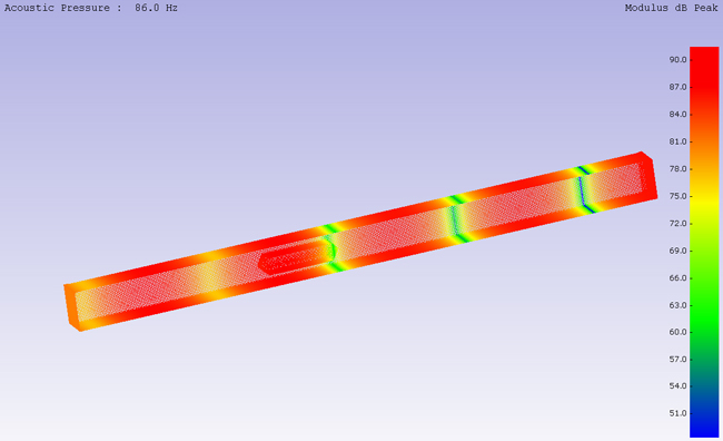
Fig. 4 perspective view – peak sound pressure level modulus for the frequency 86 Hz (in the frequency band of central frequency 63Hz) obtained by a calculation based on a Boundary Element Method (BEM) for the noise attenuator in fig. 1
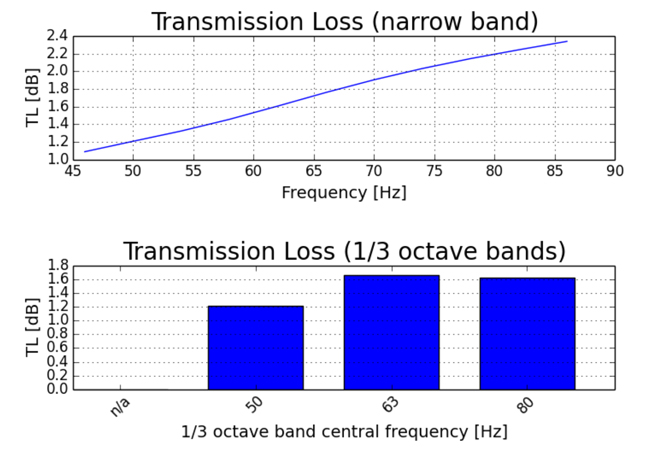
Fig. 5 transmission loss of a noise attenuator in the frequency band of 63Hz central frequency obtained by a calculation based on a Boundary Element Method (BEM) or the noise attenuator in fig. 1
- in terms of aeraulics: the total pressure loss, the maps (color contours) of various scalar indicators (e.g. pressure, speed), distribution of speed vectors, isometric lines of parameters e.g. speed
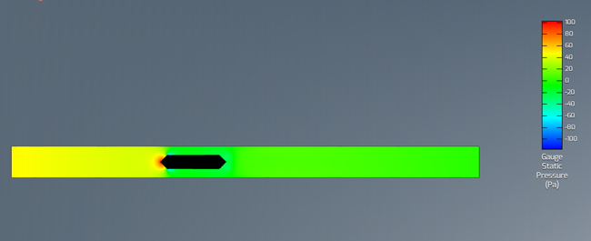
Fig. 6 longitudinal section - static pressure mapping for the noise attenuator of which the mesh is illustrated in fig .2
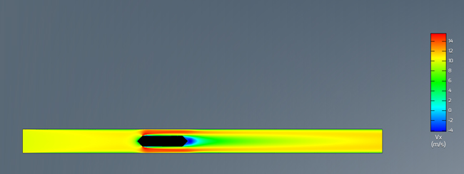
Fig. 7 longitudinal section - axial speed mapping for the noise attenuator of which the mesh is illustrated in fig .2
[1] FEM : Finite Element Method
[2] BEM : Boundary Element Method
[3] CFD : Computational Fluid Dynamics (Mechanics)