What are the input data useful for the design of a silencer ?
The input data useful for the design of a silencer are mainly the type of fluid (and its degree of physicochemical aggressiveness with respect to the envisaged silencer), its thermodynamic state (flow rate, pressure, temperature, density), the level of acoustic performance required (insertion loss, remaining sound power), the level of aerodynamic performance required (total pressure loss often called pressure drop), and the space available (dimensions of the upstream network, space available for the silencer, downstream interfacing if applicable). In very numerous cases, the reaction to fire of considered materials is also taken into account.
In the case of realizations in the food industry, in pharmaceuticals, or in hospitals, specific constraints related to hygiene are involved and may necessitate the use of particular absorbing fillings (with waterproof washable linings) or the use of stainless steels.
Other parameters may be involved such as the authorized mass, the longevity required or the available budget.
In a concrete and exhaustive way, the sizing of a dissipative silencer (i.e. a noise limiting device whose efficiency has to do with the presence of a sound-absorbing material) requires knowledge of the following input data (listed in the order of their input for a calculation with the SILDIS® software Modules 1 / 1+ / 1A Prediction of acoustic and aeraulic (aerodynamic) performance of silencers, considering for the acoustic structure of the sound-absorbing lining an assembly made up at most of a porous medium with surfacing and perforated protection, for the fluid of clean and dry air, and without change of cross section neither at the inlet nor at the outlet of the silencer other than that, linked - where applicable - to the presence of splitters with a sound-absorbing filling i.e. baffles, transverse or concentric):
- temperature
- pressure
- (in case of the presence of a porous medium):
- (as a minimum) resistivity, porosity, (and, if known) tortuosity, thermal and viscous characteristic lengths (or else designation of the nature - e.g. rock, glass, basalt, polyester, ceramic wool or foam to be precised -, trade name and density)
- thickness
- (in the event of the presence of a surfacing, if it is not modeled as a porous medium):
- superficial air flow resistance
- weight per unit area
- thickness
- (in the event of the presence of a perforated protection, if it is not modeled as a porous medium):
- designation of the geometry of the holes (e.g. circular, square, slot-shaped perforation) and their arrangement (e.g. square, hexagonal, staggered)
- diameter or side of holes / width of slots
- center distance (for slots only)
- perforation rate
- thickness
- sound power level in 1/3 octave or 1/1 octave bands at silencer inlet
- (if there is a flow):
- mass flow
- direction of fluid circulation (with respect to the direction of sound propagation: identical - if it is a discharge - or opposite - if it is a suction -
- imposed speed limit (where applicable)
- (in the case of a duct with a rectangular section):
- width [1]
- height [1]
- (in case of square section sheath):
- dimension [1]
- (in case of circular section duct):
- diameter [1]
- length of the dissipative section [2]
- (if there is a flow, with a view to calculating the total pressure loss):
- geometry (shape, dimensions) of the upstream end of the dissipative section
- geometry (shape, dimensions) of the downstream end of the dissipative section
- (if there are splitters with sound-absorbing filling i.e. baffles, transverse or concentric):
- geometry (shape, dimensions) [3]
- number and arrangement [3]
- targeted sound power level at silencer outlet (where applicable)
- acceptable total pressure loss
In the event that it is not clean dry air, the additional following input data (for gas at silencer operating conditions) would be required (in case of several components: for the resulting mixture):
- individual constant
- adiabatic constant
- density
- speed of sound
- dynamic viscosity
- specific heat at constant pressure
- thermal conductivity
This is the list of useful input data for the design of a silencer in linear regime. In the nonlinear regime, the characteristics of the acoustic excitation (nature, sound pressure levels per frequency band) must also be considered.
[1] corresponding to the internal cross section (i.e. delimited by surfaces in contact with the fluid); for a calculation with Module 1 of the SILDIS® software, this dimension is assumed to be equal, for what delimits the space occupied by the fluid, to what it is on the one hand upstream of the silencer, and on the other hand downstream of the silencer ; otherwise, i.e. in the case of a change in the dissipative section compared to upstream or/and downstream, a calculation is possible with Module 1B of the SILDIS® software: a sketch (with dimensions) of the muffler cross section is then desirable
[2] i.e. dimension without counting the upstream and downstream ends (e.g. with aerodynamic profile) not lined with sound-absorbing material; a sketch (with dimensions) of the longitudinal section of the silencer is desirable
[3] a sketch (with dimensions) of the cross section and the longitudinal section of the silencer is desirable
Which operation principle and which applications for silencers in the context of a soundproofing project ?
Silencers are devices reducing sound transmission in a duct, a pipe or an opening, without preventing the transport of a fluid. They therefore constitute basic components within the panoply of means to fight against noise both in industry, in the context of the preservation of the environment or in the building. If the operating principles (which can be combined) are mainly only two in number, the fields of application are numerous and varied.
The two main operating principles of silencers (dissipation or reflection - for reactive silencers -) refer to phenomena specifically linked to the modalities of propagation of sound waves in the ducts making aeraulic networks or pressurized fluid piping systems. The choice of one, the other or a combination of the two (in the same soundproofing device, or in the form of two distinct sub-assemblies - installed in series -) makes it possible to deal with the various problems justifying the use of such noise reduction equipment.
Principle of dissipative silencers
Dissipative silencers are those whose efficiency is based on the presence of an internal sound-absorbing lining, e.g. mineral wool (rock, basalt, glass) or polyester (more rarely: foam), maintained by a metal frame (the most often: made of steel), and which can - depending on the context - cover the (internal) periphery of a duct and/or constitute splitters (baffles) i.e. blocks between which the fluid circulates (sometimes: concentric - for a cylindrical silencer - or parallel - for a muffler with an often rectangular section, more rarely: circular - ; depending on the service conditions, a surfacing (glass clothl, fabric, metallic knit) and a perforated protection (in general: it is a steel sheet ) avoiding defibration due to erosion (related to the speed of circulation of the fluid, and sometimes to its composition). Generally effective over a wide frequency band - but with less performance at both low and high frequencies -, they are suitable for soundprrofing in many contexts:
- when the fluid is air under quasi-atmospheric conditions: the most common applications are those encountered in the building sector (aeraulic networks for air renewal and air conditioning of premises) and others, often more demanding, have to do with the industrial sector (air condensers - the number of fans to be treated can be counted by tens -, cooling towers - the diameter of the fans can exceed 10 meters, air intake of turbomachines - the inlet section of air can exceed 100 m2 -) without forgetting installations of all kinds for which fans are likely to create noise disturbance e.g. paint booths, tunnels
- for high-temperature fluids (combustion gas, steam): noise reduction devices for gas turbines and industrial chimneys for various processes, downstream stage of an exhaust silencer for a heat engine or gas decompression
Principle of reactive silencers
Reactive silencers are those whose efficiency is based on geometric variations of the internal parts e.g. modifications of section - including by means of chambers connected by tubes, presence of perforated elements through which the passage of the fluid is provided, changes in the direction of fluid flow. Generally used for low frequency noise attenuation, they are suitable for noise reduction in many contexts:
- when the fluid is air at quasi-atmospheric conditions: for compressors
- for high temperature fluids (combustion gas): upstream stage of exhaust silencer for diesel or gas engine
Domains of applications for silencers
Silencers being equipments allowing to control noise emissions in a gaseous medium, are appropriate (inter alia):
- for attenuation of the noise emissions by systems and for prevention of parasitic coupling produced by heating, ventilation and air conditioning - HVAC - equipments (they are thus useful in the context of noise reduction of equipments in residential buildings, hotels, hospitals, whether being equipment installed in an equipment room or bieng equipment installed outdoor such as heat pumps, air conditioners, air coolers ...)
- for the prevention or reduction of noise transmission through ventilation openings, from rooms with high internal noise levels (they are thus employed to prevent or limit the sound nuisance in relation to the ventilation of technical premises, of parkings, of power generation units whether cogeneration plants, emergency gensets or power plants and also in industry with respect to various processes, such as dust control facilities, chips evcuation facilities)
- limitation of air intake noise and of exhaust noise emitted by internal combustion engines (the air intake noise is usually treated with dissipative silencers while the exhaust noise uses reactive mufflers). Generating sets for the propulsion of boats as well as for the supply of electricity in the event of a power outage (e.g. in hospitals, data centers) or in a context of continuous energy production e.g. cogeneration, methanization are concerned.
- reduction of air intake noise and of exhaust noise emitted by compressors and turbines equipped with fans
- sound level decrease of industrial process control valves
Intervention of ITS with regard to application relating to silencers
With regard to the domains of application of silencers in the context of a soundproofing project, ITS can (depending on the case):
- provide advice on the choice of a noise reduction device appropriate to the context, as part of an acoustic design office assignment
- size a dissipative or reactive silencer by defining its acoustic performance (i.e. dynamic insertion loss, self-noise) and aerodynamic performance (i.e. total pressure loss) with specific software
- market the corresponding soundproofing hardware and also associated equipment: air filters for tubomachines and engines, exhaust gas pollution control systems (catalytic reduction)
Spread the word !
Which performance for an acoustic testing and measurement room ?
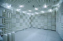
An acoustic testing room and mesurement (anechoic or semi-anechoic, including: the experimental chamber of an aero-acoustic wind tunnel) is a space in which one tries, for the purpose of research and development in acoustics (R&D), to create the conditions of an acoustic field being free (sometimes: on a reflecting plane) i.e. liberated from the limits imposed by the presence of walls.The acoustic performance of such test facilities is therefore absolutely crucial, generally taking precedence over any other consideration in the context of related projects; ITS masters all aspects of the performance of acoustic testing and measurement rooms.
The on site-verification of the performance of acoustic testing and measurement rooms (and their qualifications) can be conducted according to standard NF EN ISO 3745 Acoustics - Determination of sound power levels of noise sources - Precision methods for anechoic and semi anechoic rooms. This document is often referred to in technical specifications relating to such equipment.
ITS masters all aspects of the performance of acoustic testing and measurement rooms. |
Performance of an acoustic testing and measurement room in terms of anechoicity
The performance of an acoustic testing and measurement room (anechoic or semi-anechoic rooms, including: aero-acoustic wind tunnels), in terms of cut-off frequency (frequency above which the absorption coefficient at normal incidence of the absorbing element of the partitions is greater than 99% for walls, roof and where applicable - for anechoic rooms- floorl) is characterized by a measurement of a lining sample in a plane waves impedance tube. By extension (in fact: so shortened), the cutoff frequency is often referring to (in practice) the frequency above which the conditions inside the test room are those of a free (acoustic) field (in the case of a semi anechoic room: with a reflective floor), and sometimes: taking into account the tolerances set by the standard NF EN ISO 3745.
As an order of magnitude, a cutoff frequency below 50 Hz can be achieved with an absorbing lining with a careful design and with a careful implementation.
The performance of an acoustic testing and measurement room (anechoic or semi-anechoic rooms, including: aero-acoustic wind tunnels), in terms of quality of the free field is very frequency dependent and is primarily related to the performance of the absorbing lining (for walls, roof and where appropriate - for anechoic chambers - floor) (characterized by their absorption coefficient at normal incidence).
This performance can be expressed in terms of deviation of measured sound pressure levels with respect to the theoretical levels obtained using the law of the inverse square of the distance (i.e. in terms of deviation from the spatial sound decay in a free field) by octave or 1/3 octave bands at specified locations.
For orders of magnitude deviations of measured sound pressure levels with respect to the theoretical levels obtained using the law of the inverse square of the distance up to 1.5 dB at frequencies below 630 Hz, up to 1.0 dB at frequencies between 800 and 5000 Hz, up to 1.5 dB at frequencies above 6300 Hz can be obtained in the case of testing stations in accordance with standard NF EN ISO 3745.
An additional aspect of the performance of an acoustic testing and measurement room which may be of interest for some users of such equipment (generally: engineers and researchers in acoustics) is the convertibility: anechoic/semi-anechoic . The difference is only in the behavior of the floor: absorbing/reflecting sound; on the one hand obtaining for both configurations acoustic characteristics at the best level and on the other hand conversion methods combining safety, ease and speed must be the object of all the care in terms of design and construction to obtain a room constituting the ultimate.
In relation to the predictioon of the performance of acoustic testing and measurement rooms in terms of cut-off frequency and quality of the free acoustic field, the simulation of the sound absorption coefficient (in normal or random incidence) of multilayered structures (e.g. combining mineral or polyester wools, foams, metal plates) can be performed with the SILDIS® software, developped and edited by ITS.
Performance of an acoustic testing and measurement room in terms of sound insulation
The performance of an acoustic testing and measurement room (anechoic or semi-anechoic rooms, including: aero-acoustic wind tunnels), in terms of sound insulation is very frequency dependent and is primarily related to airborne sound attenuation of the envelope (characterized by its sound reduction index) and also the effectiveness of the vibration control device (characterized by its filtration rate).
This performance can be expressed in terms of background nosie, i.e. in terms of A-weighted overall sound pressure levels or in terms of sound pressure levels in octave bands inside the test room.
For orders of magnitude, inside the testing room, A-weighted overall sound pressure levels of 10 dBA or less or sound pressure levels in octave bands of 0 dB or less can be obtained in the case of some performing testing facilties (always with a special construction).To obtain such results, it is necessary to build an envelope limiting the transmission of airborne noise; its elements (floor, roof, walls including doors and devices for limiting the propagation of noise at the level of openings e.g. silencers, caulking) must often have an exceptional average sound reduction index; even when using high-performance acoustic structures (thick concrete, metal panels with reinforced acoustic insulation), it is often useful to design and build double-shell edifices (according to the so-called "box-in-box" principle).
In relation to the prediction of the performance of acoustic testing and measurement rooms in terms of airborne sound insulation, the sound reduction index (in diffuse field) of multilayered structures (e.g. combining mineral or polyester wool, foams, metal plates or made of plaster and masonry elements) can be performed with the SILDIS® simulation software, developed and published by ITS.
Which sound absorbing lining type "Asymmetrically Structured Absorber" in an acoustic testing room?
In an acoustic test and measurement room, pieces of foam or fibrous material (e.g. mineral wool - rock, glass - or polyester), cut from the mass or obtained from assemblies (of plates), with in some case a support and protection cover (even when there is a perforated sheet at the front) often constitutes an anechoic (i.e. avoiding the reflections of acoustic waves on the surfaces they cover: walls, ceiling, even in somes cases: ground flloring) lining.
In relation to products that can be quite different in how they are made, in shape and in frequency performance - there is usually (at least) this in common among these conventional sound absorbers:
- they are usually designated by the term "wedgel" (regardless of their effective geometry, almost always: angular)
- the lower limit of the frequency domain (often called: cut-off frequency) from which their sound absorption coefficient reaches or exceeds 99%, which is necessary to obtain, inside a room, an acoustic field as free as outdoors - in an unlimited space - (which is precisely the purpose of the implementation of a sound-absorbing lining in a room dedicated to research and development - R&D - in acoustics) is very dependent on their depth e.g. [1] 0.825 m for a cut-off frequency of 100 Hz
This characteristic of their performance poses a problem in different contexts, with regard to the thickness of conventional sound absorbers which would be required to obtain a given cut-off frequency (which must be counted twice when considering the dimensions usable in practice in the experimental chamber between parallel walls having a given spacing):
- where, taking into account the distance required on the one hand between the noise source under test and the microphones, and on the other hand between the microphones and the sound-absorbing coating, it would only allow measurements for a hardware with a size that would be too small compared to that of the hardwarel to be tested indeed
- when it would require a distance between walls greater than what is possible
This is why, whether it is a project to build a new acoustic testing and measurement room, or to retrofit an existing test facility (and then: there is no not uncommon for the search for a lower cut-off frequency to be topical, with respect to what the problem of available space is further increased), an "assymetrically structured absorber"constitutes a particularly suitable sound-absorbing lining since it allows (for cut-off frequency) obtaining:
- 125 Hz for a thickness of 0.53 m
- 100 Hz for a thickness of 0.65 m
- 80 Hz for a thickness of 0.78 m
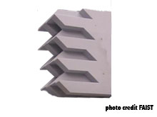
The asymmetrically structured sound absorbers marketed by ITS (available in 3 thicknesses, as mentioned above) are machined from blocks of non-flammable, light-coloured foam (it is possible to add, at the front, a perforated metal protection).
As their name suggests, asymmetrically structured sound absorbers have an angular corrugation, i.e. a form of regularity in the variation of the thickness of the material, which is different from that - less sophisticated - of conventional wedges.
Such a choice of asymmetrically structured sound absorbers is appropriate in all cases where an absorbent lining with both a very good absorption factor and a thickness less than that of a conventional wedge is required, at a reasonable supply and installation cost: for acoustic testing and measurement rooms such as anechoic or semi-anechoic rooms with which universities, engineering schools and acoustics laboratories are often equipped..
|
|
|
ITS masters all aspects of the choice of an anechoic lining "asymmetrically structured absorber" for an acoustic testing and measurement room.
Spread the word !
Which "broadband compact absorber" anechoic lining in a testing and measurement acoustic room ?
The sound-absorbing lining of an acoustic testing and measurement room must, in a frequency range of interest sometimes as wide as 50 Hz - 20 kHz, be sufficiently effective to make negligible the impact of the partionl (wall, ceiling, and sometimes: floor) by which it is backed, with respect to the concept of free acoustic field, basing many metrological methodologies.
In many contexts, the thickness available for such a functionality to be ensured is not unlimited, whether it concerns the construction of new rooms or the renovation/improvement of existing means. Among the causes of this situation:
- the total space available to accommodate the acoustic testing and measurement room (allowing the opening of large doors, providing space for the storage - outside - of test specimens or equipment - subject of the tests - sometimes bulky, and making it possible to set up an adjoining room for the personnel assigned to the measurements) is often, dimensionally, constrained by its environment
- the volume available for the acoustic tests and measurements inside the room (taking into account the distances required on the one hand between the equipment under test and the measurement envelope - where the microphones are placed - and on the other part between it and the end of the sound-absorbing lining) is all the less important as this covering is thick (the occupied depth counts double between facing walls)
So, it is not rare that the implementation of conventional sound-absorbing wedges (whose cut-off frequency i.e. the lower limit for which the sound absorption coefficient reaches 99% is proportional to the wavelength corresponding to the lowest frequency of interest) are considered cumbersome when it comes to obtaining low frequency performance and their thickness is prohibitive, since would be necessary (with a sound speed of 340 m/s):
- 0.85 m for a cut-off frequency of 100 Hz
- 1.70 m for a cut-off frequency of 50 Hz
This is why a sound-absorbing lining for an anechoic room, whose efficiency at low frequency is not linked to a very high thickness of material, is of certain interest for many applications: this is the reason for being of a broadband compact absorber.
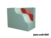
It comes to modules, in the form of boxes, the filling of which is carried out by means of a multilayered acoustic structure, with from the back to the front:
- a dissipative material (mineral or polyester wool, foam)
- a metal plate, which combined with the layer on the back, behaves like a resonator absorbing low frequency sounds
- a dissipative material (mineral or polyester wool, foam) with perforated metal protection for the absorption of medium and high frequency sound
Nature and thickness of the components of broadband compact absorbers can be adapted according to the desired acoustic performance (and also to other constraints e.g. fire behavior). In all cases, the thickness of the assembly does not exceed (depending on the model) 0.25 m or 0.35 m and it makes it possible to obtain an anechoicity characteristic suitable for all known requirements in this area.
Such a choice is appropriate in all cases where it is looked for an absorbing lining having both a very good absorption factor, with a minimum thickness, with minimum a cost and with minimum installation costs. The lining of the type "Broadband Compact Absorber", abbreviated BCA is plane: it is particularly recommended for testing rooms such as anechoic or semi-anechoic rooms (including: the experimentation chamber of aero-acoustic wind tunnels), particularly in the automotive industry.
|
BCA |
|
ITS masters all aspects of the choice of a "broadband compact absorber" anechoic lining for an acoustic testing/measurement room.
Spread the word !
More Articles
- Which sound absorbing linings in an acoustic testing and measurement room ?
- What are the useful input data for choosing a sound-absorbing lining in an acoustic test and measurement room ?
- What measurements in relation to the spatial sound decay in a room?
- What measurements in relation to the reverberation of a room?
Page 3 of 12