Which sound absorbing linings in an acoustic testing and measurement room ?
General information relating to sound-absorbing linings for acoustic testing and measurement rooms
Sound-absorbing inings for an acoustic testing and measurement room aim to obtain, inside a building, free acoustic field conditions, such as could be obtained outside, in an space being unlimited (but subject to bad weather, which generally does not accommodate metrological practice relating to acoustics e.g. in a research and development - R&D - context).
When they do not include a resonator, the airflow resistance and the thickness are therefore crucial acoustic characteristics of such coverings, which are then fibrous or made of open-cell foam for such applications.
This is why a sound-absorbing lining for an acoustic testing and measurement room is commonly made up of pieces of mineral (e.g. rock or glass) wool, polyester wool or foam of sufficiently low density so that the associated resistivity does not oppose too much the penetration of acoustic waves, even in the case of the important thicknesses which are required for an effectiveness in low frequency according to such a principle of action.
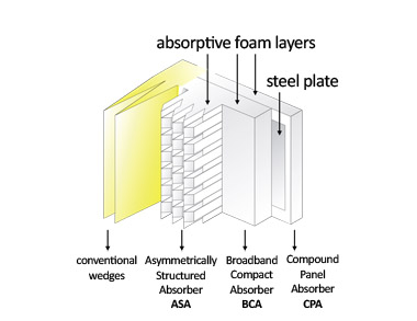
In some cases, absorbent linings for acoustic testing and measurement rooms are in the form of wedges (i.e. pyramid-shaped subsets) while in other cases, compact absorbers or asymmetrical structured absorbers (ASA)are used.
The difference between the first (conventional wedeges) and the last is not only due to their dates of placing on the market (separated by several decades), but also to their length (the sophistication of the geometry of the ASAs allowing a reduction of this fundamental parameter for the layout of laboratories).
As for absorbing linings for testing rooms such as anechoic or semi-anechoic rooms (including: aero-acoustic wind tunnels) are concerned, they generally consists of multilayer modules sometimes (quite often: made of mineral wool or of polyester wool or of melamine foam) often covered by a surfacing (most often: a fiber glass or a polyester cover) and (in many cases) and by a perforated protection (mostly: galvanized or painted steel). A powder coating usually provides the best protection against corrosion: classification up to C5 according to ISO 12944 while providing a visula aspect appropriate for the the context.
In some cases, the frame of the plane absorbing lining in a test room can be made of stainless steel (SS 304, SS 316) or aluminum.
As required, the absorbing lining may be, for some applications, protected by a waterproof surfacing (polyurethane film and for extreme cases: painting).
In order to increase the absorption coefficient in a given frequency range, an intermediate plate (usually made of steel) and also an additional spacing absorbent layer may be inserted into the absorbing linings for test rooms, the performance such absorbing panels then being (partially) based on the effect of resonant membrane (also known as resonator).
The prediction of the performance of plane absorbing linings for testing rooms can be performed with the simulation software SILDIS®.
Verification of acoustic performance of sound-absorbing linings for acoustic testing and measurement rooms can be made in accordance with ISO 354 Acoustics - Measurement of sound absorption in a reverberation room or in accordance with the standard NF EN ISO 10534-1 Acoustics - Determination of sound absorption coefficient and impedance in impedance tubes - Part 1: Method using standing wave ratio.
Comparative performance of sound-absorbing linings for acoustic testing and measurement rooms
The comparative performance of sound-absorbing linings for acoustic testing and measurement room is illustrated below (Faist range), with respect to the two fundamental characteristics:
- thickness (for maximizing the space available inside the room and for minimizing its footprint, all other things being equal)
- random incidence sound absorption coefficient (in a reverberant room)
|
|
|
. |
 absorbing linings for anechoic chambers
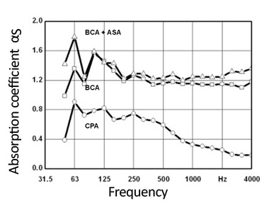 absorbing linings for acoustic testing and measurement rooms
ITS masters all aspects of the choice of a sound-absorbing lining for an acoustic testing and measurement room.
Spread the word !
What are the useful input data for choosing a sound-absorbing lining in an acoustic test and measurement room ?
The input data useful for the implementation of an absorbing lining in an acoustic testing and measurement room are primarily:
- the use of the room: normative requirements are associated with anechoic or semi-anechoic rooms which differs only in the properties of the ground (respectively absorbing or reflecting sounds); for users (in general: technicians and engineers or researchers in acoustics) needing a versatile facility (for their research and development - R&D - works), the convertibility of a room (with respect to anechoicity: full or half) can be obtained according to different principles and means, more or less sophisticated depending on the periodicity of the conversions and on the time allowed to switch from one configuration to another
- the envisaged type of metrology: measuring the noise emitted by accelerating road vehicles requires a very specific environment (according to standard ISO 362-3, with a large number of aligned microphone sensors), other applications having - for most of them - in common to refer to standard ISO 3745, with a more limited number of sonometric lines - for sound pressure level assessment - and a measurement surface that is often parallelepiped or shaped semi-circular
- the nature of the objects under test (size, sound spectrum): frequency band of interest, distances on the one hand between noise source and microphones and on the other hand between microphones and sound-absorbing lining are linked, the desire to have propagation conditions perfectly reproducing those of the free acoustic field involving testing means all the more voluminous and important as the tested object is large, and as the lower limit of the frequency domain of interest is low
- the physical setting (area of available surfaces, acceptability of overweight for supports for the walls or for the roof and when applicable for the floor)
In very many cases, the reaction to fire of considered materials is also taken into account as well as considerations of appearance (even if the architectural bias is generally not as important as acoustic performance, colors and materials count when it comes to creating an atmosphere appropriate to prolonged work and worthy of a showcase for sometimes high-ranking visitors).
Specific constraints related to resistance to impacts or to weather damages may necessitate the use of particular absorbing linings (with waterproof, washable cover) or the use of stainless steels.
Other parameters may be involved such as the authorized mass, the required longevity or the available budget as well as (sometimes) thickness of the lining.
In the case of projects in the automotive industry sector, or for other industrial applications related to the transport or energy industries sector there is a utility, when it is not an absolute necessity, to have in semi-anechoic or semi-anechoic rooms, plane absorbers (e.g. apart from the advantage that this presents in terms of durability in hostile environments, to avoid the generation of noise linked to the airflow on surfaces with corrugations, such as in the case of conventional wedges). The walls of the experimental chamber, and sometimes other sections of the aeraulic circuit of aeroacoustic wind tunnels can advantageously be covered with a multilayer lining which combines dissipative materials (foams, wools) and a metal membrane to obtain an acoustic absorption coefficient of 100% over a frequency range as wide as is desirable for envisaged metrology.
Whatever the context, ITS masters the aspects of the question of useful data for choosing the sound-absorbing lining for an acoustic room (test-measurement).
Spread the word !
What measurements in relation to the spatial sound decay in a room?
General considerations in relation to the measurement of the spatial sound decay in a room
A value of the spatial decay of the sound pressure level by doubling the distance too small (illustrating excessive sound waves reflections reverberation phenomena e.g. on hard surfaces) can impair the acoustic comfort in some spaces (given their intended purpose) and (in some cases) conformity e.g. in work premises:
- shared offices (e.g. open spaces)
- dining rooms
In France, the measurement of the spatial sound decay in a room is carried out in accordance with the appendix of the Decree of august 1990 the 30th used for the implementation of the article R. 235-11 of the Labor code and related to the reverberation limitation of working premises or with the standard (which is often preferred) ISO 14257 Acoustics – Measurement and parametric description of spatial sound distribution curves in workrooms for evaluation of their acoustical performance.
Practical aspects in relation to the measurement of the spatial sound decay in a room
- production of the acoustic field: the acoustic field is usually produced by an omnidirectional pink noise source
- measuring equipment: the acoustic measuring equipment generally consists of a sound level meter (with a microphone) and of a calibrator
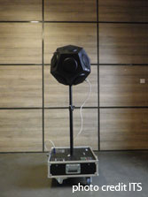
ITS omnidirectionnal noise source for room spatial sound decay measurement |
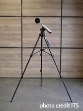
ITS sonometer for room spatial sound decay measurement |
- transfer and analysis software: a transfer and analysis software is generally used, allowing a deferred exploitation of recordings carried out on site
- evaluation of sound spatial decay: this is the difference in decibels between the sound pressure level in a given octave band and for a microphone position located at a given distance from the reference sound source and the sound power level of the reference sound source in the same octave band
- determination of the spatial decay of the sound pressure level by doubling the distance: this is the slope, in decibels, of the spatial sound decay curve in a given range, when the source distance doubles
Qualitative aspects relating to the measurement of spatial sound decay in a room
Depending on the size of the premises, the quality of the spatial sound decay measurements may require, for the noise generator, a set of loudspeakers:
- omnidirectional, then installed at a height compatible with the presence of furniture (e.g. in an open space)
- forming a half-sphere, then placed on the ground
For quality spatial sound decay measurements:
- the sound level meter used must be duly calibrated and verified
- nothing beats a technician experienced in physical measurements, specialized in instrumental techniques who will be able to choose, for the best possible determination of the DL [1] parameter:
- the most appropriate areas for the positioning of the noise generator and the microphone sensors
- the best measurement paths, in adequate numbers and with as many ideally spaced points as desired
- the best after-treatment of recordings of emission/reception measurements of sound signals
Of course, that an acoustician with a degree in building physics can be able, within the framework of an acoustics engineering mission, to analyze the results of measurements of the spatial sound decay of premises and not only to adopt a position on conformity, but also to propose initiatives for actions aimed at improving the situation, and that he also - as at ITS - has solid experience in solving problems of noise reduction and improvement of acoustic comfort is a definite advantage.
ITS masters all aspects of spatial sound decay measurements in a room, with services whose quality is regularly assessed and certified in accordance with the requirements of the standard ISO 9001.
Spread the word !
[1] spatial sound decay rate, expressed in dB(A) per doubling of distance (with respect to a reference sound spectrum)
What measurements in relation to the reverberation of a room?
General considerations relating to measurements in relation to the reverberation of a room
A value of the reverberation time too high (illustrating excessive reverberation phenomena) can impair the acoustic comfort in some spaces (given their intended purpose) and (in some cases) the conformity.
Measurements related to the reverberation of a room are therefore useful in different contexts:
- for a diagnosis, on the occasion of which the results of measurements can be compared with reference values, regulatory or normative:
- for structures hosting young children
- for educational institutions: schools, universities; both for premises dedicated to learning and training and for those intended for catering
- for healthcare facilities; both for premises accessible to the public and for those dedicated to professionals
- for work premises (including offices, e.g. when it comes to open spaces - without forgetting canteens -)
- for the verification of the effectiveness of soundproofing actions, at the end of their implementation
Practical aspects of measurements in relation to the reverberation of a room
In France, the measurement of the reverberation time is carried out in accordance with the standard NF S 31-057 - Acoustics - Verification of the acoustic quality of buildings or with the standard (which is often preferred) NF EN ISO 3382-2 - Acoustics - Measurement of acoustic parameters of rooms - Part 2: Reverberation time of ordinary rooms.
- production of the acoustic field: the acoustic field is usually produced by an omnidirectional pink noise source (interrupted noise method)
- measuring equipment: the acoustic measuring equipment generally consists of a sound level meter (with a microphone) and of a calibrator. If used, the equipment for measuring the temperature and humidity of the room is often a thermo-hygrometer.
|
ITS omnidirectionnal noise source for room reverberation time measurements |
ITS sonometer for room reverberation time measurements |
- transfer and analysis software: a transfer and analysis software is generally used, allowing a deferred exploitation of recordings carried out on site.
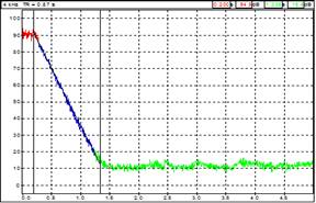
- reverberation time (reverberation time) evaluation: the reverberation time is the time needed for the sound pressure level to decrease by 60 dB after the noise source is turned off in a room
- example of recording of the temporal sound decay allowing the determination of the reverberation time TR for the frequency band 4 kHz (in this case: TR = 0.87 s) with an evaluation range greater than that envisaged in the standard NF EN ISO 3382-2)
(measured) reverberation time
Methods and quality of measurements in relation to the reverberation of a room
From the results of measurements in relation to the reverberation of a room depends the relevance:
- of comparisons with reference values, for the purpose of verifying the compliance of premises
- of actions that may be necessary
As far as measurement methods are concerned, standard NF EN ISO 3382-2 - Acoustics - Measurement of acoustic parameters in rooms - Part 2: Reverberation time in ordinary rooms distinguishes three of them:
- control method: the control method is suitable for evaluating the amount of absorption of the room for noise control purposes, and for control measurements of airborne sound insulation and impact sound insulation. It should be used for ISO 10052 measurements ; measurements based on control method are made in octave bands only.
- expert method: the expert method is suitable for checking the performance of buildings against the specifications of the reverberation time or the absorption of the room. It should be used for measurement in all parts of ISO 140 that mention measurements of reverberation time.
- precision method: the precision method is suitable when high measurement accuracy is required
Comparisons of the number of positions and measurements against the minimum number of positions and measurements according to standard NF EN ISO 3382-2 can be made as follows:
| Control | Expertise | Precision | |
|---|---|---|---|
| Source and microphone combinations | 2 | 6 | 12 |
| Source positions | ≥1 | ≥2 | ≥2 |
| Microphone positions | ≥2 | ≥2 | ≥3 |
| Number of decays in each position (interrupted noise method) | 1 | 2 | 3 |
It goes without saying that it is preferable that measurements related to the reverberation of a room are carried out:
- by a skilled workforce such as a physical measurement technician specializing in instrumental techniques, with years of practice
- with duly calibrated and verified sound level meters
- by a structure having:
- ISO 9001 certification for the quality management system of its services
- a human resource capable of providing a solidly founded opinion with regard to both the assessment of the conformity of the premises and the solutions for improving their quality - such as an acoustician with a diploma in building physics, with a long experience of solving problems related to the acoustic comfort of premises of all kinds -
ITS has all these assets: ITS masters all aspects of measurements related to the reverberation of a room.
Spread the word !
Which acoustic performance levels and criteria for workrooms?
The question of acoustic performance levels and criteria for work premises is central, when one considers the protection of workers against noise-related risks.
The Decree of August 1990 the 30th used for the application of Article R. 235-11 of the Labor Code and relating to the reverberation limitation of working premises is applicable to the construction or layout of working premises, where envisaged machinery and equipment may expose workers to a daily sound exposure level greater than 85 dB (A).
This document establishes the minimum characteristics that these rooms must have in order to reduce the reverberation of the noise on the walls when this must significantly increase the level of noise exposure of workers (the increase in exposure is appreciated in relation to what would be the exposure of each of the workers in the same premises ideally treated, that is to say without any reverberation).
The technical requirements of this decree are applicable where it is established that reverberation, as assessed by a predictive acoustic method, would result in an increase of the daily sound exposure level of a worker equal to or greater than 3 dB(A).
In what follows:
- S represents the floor area of the room (in square meters)
- DL is expressed in dB (A) per distance doubling
The walls of such spaces shall be so acoustically treated that the decay of the sound level by doubling the distance to the source measured in the empty space without any production machine or installation reaches at least the value given by a rule related to the workroom floor area.
- DL = 2 dB(A) if S ≤ 210 square meters
- DL = 1,5 log S - 1,5 if 210 < S ≤ 4600 square meters
- DL = 4 dB(A) si S > 4600 square meters
When the decrease in the noise level by doubling the distance at the source is measured in the room after installation of the production machinery and apparatus, the DL value which must be at least reached is given by another rule related to the workroom floor area.
- DL = 3 dB(A) si S ≤ 210 square meters
- DL = 1,5 log S - 0,5 si 210 < S ≤ 1000 square meters
- DL = 4 dB(A) si S > 1000 square meters
ITS masters all aspects of the question of acoustic performance levels and criteria for work premises:
- on-site measurements (by a technician qualified in physical measurements, specialized in instrumental techniques, with a duly calibrated and verified sound level meter) of the decrease in the sound pressure level by doubling the distance to a noise generator at distances standardized for the determination of the DL parameter mentioned above
- comparison with the regulatory values depending on the ground surface of the room and according to its lay-out status
- study of ways for improvement and advice for bringing work premises into compliance with the question of noise; simulation of the acoustic performance of different technical solutions (ceiling and other suspended sound-absorbing elements, wall cladding for soundproofing, noise barriers)
- marketing of noise reduction equipment and soundproofing work
Spread the word !
More Articles
- Wich acoustic performance levels and criteria for school premises?
- Wich acoustic performance levels and criteria for offices and associated areas or for other tertiary buildings excluding school premises?
- Wich efficiency for the reverberation control of a room ?
- Why choose baffles made of melamine foam, rather than any other suspended baffle?
Page 4 of 12