Silencers for high temperature industrial applications are noise limitation devices often required (in application of regulations), both for the protection of workers (the aim is to preserve their hearing capacities: Directive 2003/10/EC of the European Parliament and of the Council, of 6 February 2003, concerning the minimum health and safety requirements, relates to it) and for the protection of the environment (the aim is to preserve the harmony of the soundscapes, resulting from the superimposition of natural sounds and noise emissions related to human activities: the Order of 23/01/97 relating to the limitation of noise emitted into the environment by installations classified for the protection of the environment has, in this context, all its importance).
General considerations relating to silencers for high temperature industrial applications
In the filed of silencers , two categories of high temperature industrial applications are recurrent:
- aeraulic networks relating to combustion processes (e.g. exhaust lines of heat engines and gas turbines, industrial chimneys downstream of various processes - including the incineration of waste -; the noise reduction device is according to where appropriate, installed (in a horizontal position, possibly combined with a Catalytic Reduction System - SCR - for gas pollution control) upstream of the chimney or (in a vertical position) in the chimney (unless it constitutes a muffler+chimney set). Depending on the performance required, a single muffler is appropriate to satisfy the objectives or two mufflers are required.Their installation - in series - is not always direct connection:
- with regard to an exhaust system for a heat engine, a primary silencer (e.g. reactive) may be installed upstream of a pollution control device - being then used for the mixture with the combustion gas of a compound - e.g. urea - suitable for chemical reactions based on the reduction of polluting emissions, while a secondary silencer (e.g. absorptive) can be installed downstream
- with regard to a large capacity gas turbine exhaust system, a primary silencer (e.g. dissipative, sized to be effective at low frequency) may be installed (with a horizontal gas flow) upstream of a stack while a secondary silencer (e.g. dissipative, dimensioned to be efficient at medium and high frequencies) will be integrated into the stack (therefore: with a vertical gas flow)
- steam depressurization circuits (as produced by boilers e.g. Heat Recovery Steam Generators - HRSG -; the silencer often constitutes (possibly with a rainscreen device - elbow or cap -) the last component of the system (i.e. being the furthest downstream, allowing the release of the gas originally under pressure). Whatever the principles basing its effectiveness, a discharge silencer always comes in the form of a single device (often: multiple staged, but with a single envelope - forming a whole -)
Regarding silencers for high temperature industrial applications, they usually consist of a double shell outer casing (mostly with the outer shell made of non-stainless steel and with the inner shell made of stainless steel) and of an absorbing filling (quite often: mineral wool) covered by a surfacing (mostly: a glass fabric) and also by a perforated protection (mostly: made of stainless steel). For the outer casing, if required: a powder coating usually provides the best possible protection against corrosion: classification up to C5 according to ISO 12944.
In terms of design and construction too:
- with regard to simple dissipation silencers, they are soundproofing equipment belonging to the category of dissipative silencers for which the sound absorption material is placed exclusively on the inside of the outer envelope. In most cases, such silencers are round and are intended to be inserted in networks with ducts being themselves of circular cross section (silencers with rectangular cross section, possibly square can be envisaged in some cases and are intended to be inserted into networks of ducts being themselves of rectangular or enventually square cross section). The acoustic performance of such silencers (insertion loss) is highly dependent on the considered frequency and is linked to the fluid velocity, to the acoustic thickness of the lining, its nature (in particular: the flow resistance of the filling and of its covers if any), to the free inner dimension for the passage of fluid, and also to the length of the silencer. Such silencers are characterized by a total pressure loss (also called pressure drop) being low because exclusively dependent on the roughness of the walls and on the length of the silencer (usually negligible if the flow velocity of the fluid is low enough). Such devices are often considered:
- for the soundproofing of industrial chimneys, the effectiveness being - of course - increasing with the length of the sound-absorbing lining (so, all things being equal: better for high chimneys) but decreasing with the diameter (when the opposite absorbing surfaces are further apart)
- as secondary silencers of an exhaust line of diesel or gas engines (what has been said previously about the variation in efficiency as a function of geometric characteristics is also applicable here
- with regard to splitter silencers (also called baffle silencers), they are soundproofing equipment belonging to the category of dissipative silencers for which the sound absorption material is held in frames (usually metallic: in non-stainless steel) forming splitters between which the fluid flows. Most of the time, such silencers have a rectangular cross section and are intended to be inserted into networks of ducts being themselves of rectangular cross-section (silencers with circular cross-section, with circular central splitter and, where appropriate with one or more ring-shaped intermediate splitters can be envisaged in some cases and are intended to be inserted into networks of ducts being themselves of circular cross-section). The acoustic performance of such silencers (insertion loss) is very dependent on the considered frequency and is related to the fluid velocity, to the thickness of the splitters (baffles), to their nature (including: fow resistance of the filling and of its cover if any), to their spacing, as well as to the length of the silencer. Such silencers generate a total pressure loss (also known as pressure drop) mainly related to the thickness of the splitters, to their spacing, and also to their geometry (profiling of upstream and downstream extremities if any) as well as to the length of the silencer. Such devices are often considered:
- with a cylindrical shape: for silencers of small capacity gas turbines (i.e. with a power of a few MW), for secondary silencers of exhaust lines of internal combustion engines, for the downstream stage of silencers for (saturated or superheated) steam vents
- with a rectangular shape: for silencers of large capacity gas turbines (i.e. with a power of a few tens or a few hundreds of MW), for noise attenuation devices for smoke treatment facilities in industrial plants for incineration of household waste
- with regard to reactive silencers (whose operating principle is based on reflections of acoustic waves due to geometric discontinuities, e.g. changes in the section of the ducts, including when passing through perforated sheet metal, changes in the direction of circulation of the gas flow) they are made in the form of chambers connected by tubes (with or without perforations) whose all dimensions impact performance. In general, a cylindrical envelope (but can also be parallelepipedic, e.g. when it comes to an installation on the roof of a container housing a generating set) is compartmentalized with, depending on the case, one two or three chambers (when carried out with appropriate material, peripheral insulation can reduce skin temperature and limit sound transmission through the silencer walls, which is highly undesirable). Since such noise reduction devices are (mainly) effective only at low frequencies, they can be supplemented (sometimes: with a common envelope, to form a whole which is a reactive/dissipative silencer) by a subassembly ( located downstream) consisting of a sound-absorbing lining on the one hand peripheral and on the other hand constituting a central splitter)
- with regard to discharge silencers, the upstream part (called the expander) is perforated (in the form of a tube with holes drilled in its wall, or in the form of structures - sometimes: concentric, for a multi-stage device - specially machined). Subject to thermodynamic conditions appropriate to such a phenomenon, the fluid velocity therein reaches the speed of sound - and such a device regulates the mass flow -. Often, such a device for reducing the acoustic power of a jet is completed (in the same envelope, constituting a single device) by a dissipative module (located downstream) with a sound-absorbing lining:
- possibly in the form of concentric rings
- possibly in the form of more or less parallelepipedal separators (with rounded edges)
|
|
|
|
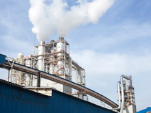 a steam depressurization vent is a common case where a silencer for high temperature industrial application is required
 Specificities of sizing and construction of silencers for high temperature industrial applications
The sizing and construction of silencers for high temperature industrial applications must take into account many specificities:
- performance issues:
- in terms of acoustics: noise sources are generally very powerful, often beyond 130 dB(A) ref. 1 pW and the sound level objectives to be achieved, even ordinarily, require reductions in sound power level in a very wide frequency domain (in low, medium and high frequencies), which can reach several tens of dB, which is considerable
- in terms of aerodynamics: not only must the total pressure loss of the soundproofing devices that are the silencers not affect the proper functioning of the installation, but - what is more - it must be as low as possible when it impacts the performance of energy production facilities, with all the financial implications
- design issues:
- the flow rates involved are often very high (several hundred kg/s for a high-capacity combustion turbine); the decrease in the density of the fluid induced by the high temperature implies very high volume flows, and therefore, even with large sections for soundproofing equipment, high speeds:
- influencing the sound propagation conditions in the internal parts of silencers, with or without the presence of sound-absorbing linings
- inducing significant self-noise (due to flow), which should not impair the overall performance of the device
- involving often undesirable head losses
- likely to cause erosion of the sound-absorbing linings, if they are not protected by surface layers which are not too much opposing the penetration of sounds, otherwise the acoustic performance would be degraded
- (in the case of dissipative silencers) the temperature also has an effect on the behavior of materials capable of absorbing sound, e.g. the resistance to the passage of air is, under service conditions, very different from that measured in the laboratory under ambient with the following consequences:
- a decrease in the possibility for sound to penetrate the linings likely to absorb it (and this is obviously unfavorable, especially in the case of very thick linings)
- an increase in the complexity of the calculations (e.g. in the case of a chimney with an internal peripheral lining that absorbs sound, the temperature gradient with the exterior - which must be the subject of iterative calculations - induces a variation in its acoustical behavior, which makes the concept of homogeneous, isotropic material quite imperfect to account for reality)
- an increase in the uncertainty related to performance prediction, which requires specific simulation tools: the prediction of the acoustic and aeraulic performance of dissipative and reactive silencers for high temperature industrial applications can be carried out with the simulation software SILDIS® [1], or with alternative means of calculation also available to ITS [2] [3] [4].
- the flow rates involved are often very high (several hundred kg/s for a high-capacity combustion turbine); the decrease in the density of the fluid induced by the high temperature implies very high volume flows, and therefore, even with large sections for soundproofing equipment, high speeds:
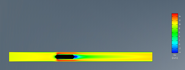
Silencer consisting of a single splitter with profiled upstream and downstream edges - axial velocity mapping (longitudinal section of a rectangular duct, result of a simulation by ITS [2])
- resistance of materials and assemblies issues (in relation to temperature resistance and also in relation to problems of metal expansion). In some cases, all the metal parts of dissipative silencers for high temperature industrial applications can be made of stainless steel (304 stainless steel, 316 stainless steel, 321 stainless steel). It is possible, when required, to build exhaust silencers for heat engines with steel grades such as P265GH (1.0425), 16Mo3 (1.5415), AISI304 (1.4301/1.4307), AISI316 (1.4571/1.4404).The complexity of the work of calculation, study, manufacture and control of depressurization silencers is further increased when they are subject - whatever the reason - to the rules applicable to pressure vessels.
[1] cf. SILDIS® simulation software
[2] FEM : Finite Element Method
[3] BEM : Boundary Element Method
[4] CFD : Computational Fluid Dynamics (Mechanics)