The prediction of acoustic and aeraulic (aerodynamic) performance of silencers is a recurring task for many acousticians and for other technicians and engineers less specializing, either in a context of noise control engineering design services and studies or in the context of R&D projects e.g. machines soundproofing, sound emissions limitation for air handling (e.g. air conditionning facilities) and pressurized fluids networks (both in building and industrial sectors).
Based on Excel, the Module 1 / 1+ / 1A of the calculation software SILDIS® allows the prediction of acoustic and aeraulic (aerodynamic) performance of silencers in a simple and safe way.
Scope of computation of acoustic and aeraulic (aerodynamic) performance of silencers with Module 1 of software SILDIS®
Basically, the prediction of acoustic and aeraulic (aerodynamic) performance of silencers with the Module 1 of the software SILDIS® is relating to the design of devices reducing the acoustic transmission in a duct, a pipe or an aperture, without preventing the carriage of the fluid, when they are dissipative, i.e. attenuating the wideband sounds with a relatively low pressure loss and converting partially the acoustic energy into heat by friction on tubes having a porous (e.g. fibrous) structure.
The acoustics calculation software SILDIS® allows also simulations for soundproofing hardware with resonant effects e.g. when plates are envisaged (then: covering a porous medium) or when cavities are involved e.g. with the so-called (due to their overall aspect) "Pine Tree" splitters producing an acoustic attenuation from weakly damped resonances of elements containing absorbing materials, then installed at the rear of chambers or laterally.
Applications of the prediction of acoustic and aeraulic (aerodynamic) performance of silencers with Module 1 of software SILDIS®
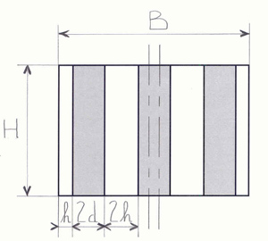
Fig. 1 Dissipative silencer with a rectangular cross-section (splitter silencer)
Various applications are possible for the prediction of acoustic and aeraulic (aerodynamic) performance of silencers with the Module 1 of the software SILDIS®, as long as it comes to obtaining a sound transmission loss by the means of the implementation of a silencer possibly included in an industrial building, a booth, a wall, a screen (for the sake of soundproofing) e.g. for protection of workers against noise exposure, preservation of sound environment (e.g. in energy sector), on the occasion of projects relating to acoustic measurement rooms or test benches, for the purpose of acoustic comfort in buildings.
Whatever the context, the flexibility of the software allows to account properly the situations commonly encountered when it is a question of predicting and/or limiting the noise impact of facilities.
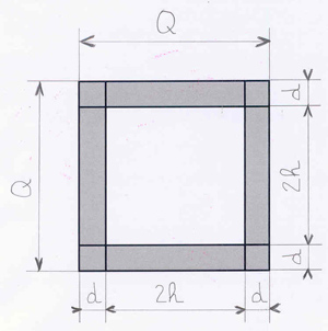
Fig. 2 Dissipative silencer with a square cross-section
In this field, it notably comes often to:
- ventilation of enclosures and/or air inlets for thermodynamic processes involving various noisy equipments such as fans, aerocondensers, engines, gas turbines (including combustion air intakes) …
- ventilation of test benches and/or air vents for thermodynamic processes of test benches …
- noise reduction of stacks, engines and gas turbines exhaust lines, fluid depressurization vents …
- sound impact limitation for air conditioning systems and piping systems of all kinds …
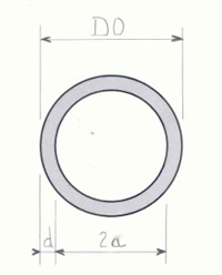
Fig. 3 Dissipative silencer with a circular cross-section: without pod (e.g. for air-conditioning or ventilation network)
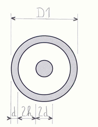
Fig. 4 Silencer with a circular cross-section: with pod (e.g. dissipative stage in a muffler)
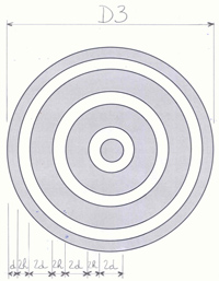
Fig. 5 Dissipative silencer with a circular cross-section: with pod and with concentric splitters
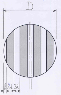
Fig. 6 Dissipative silencer with a circular cross-section: with non concentric (transverse) splitters
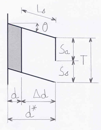
Fig. 7 Silencer: with hollow splitters of thickness 2d* (with rear sound absorbing lining)
Silencers mountings and geometry for which acoustic and aeraulic (aerodynamic) performance can be predicted with Module 1 of software SILDIS® are numerous, as detailed in User’s manual for the software SILDIS® [1].
Many configurations frequently used for silencing devices applied in the context of industrial soundproofing or for acoustic comfort in buildings can be simulated, e.g. when involving casings with a cross section possibly rectangular (cf. fig. 1), square (cf. fig. 2) or circular (cf. fig. 3, cf. fig. 4, cf. fig. 5, cf. fig. 6) and a sound absorbing fillings package of variable shape including linings and/or splitters i.e. baffles (depending on the case: with a single thickness d or with a double thickness 2d) either plane (cf. fig. 1, cf. fig. 6) or curved (cf. fig. 3, cf. fig. 4, cf. fig. 5) - many variants can be considered, depending on the number and the arrangement of absorbing splitters e.g. when ring-shaped - then with single airways h or with double airways 2h (2a in case of the absence of pod for the dissipative silencer with a circular cross section, as illustrated in figure 3) ; for cylindrical silencers (of which cross section is round), pod can be either solid or hollow.
Whereas applications in the building sector often involve the recourse to silencers with mountings and geometries as shown on figures 1 (with a variable number of splitters) to 4, practices relating to industrial soundproofing make use of a more extended variety of combinations of cross section shapes and of sound absorbing filling arrangement (figure 5 and 6 are illustrating possible designs for combustion turbine exhausts of moderate capacity - a few MW - or for downtream stage of vent silencers, the number of baffles or of absorbing rings being adjusted depending on the needs).
Moreover, for special facilities, where the fluid carried in the ducting network (and therefore: in the silencer), is significantly agressive from a physico-chemical point of view, and thus likely to dammage sound absorbing fillings if directly exposed to the flow, the baffles surface which can be accounted is not necessarily plane, but possibly with cavities hosting absorbing layers: apart from the thickness of the splitters 2d*, the number of parameters to be accounted then increases as dimensions like Δd, Ls, Sa, Ss (T), Θ should be considered in case of rear implementation of an absorber (cf. fig. 7) or other dimensional characteristics of the same kind in case of a lateral implementation (such devices are not purely dissipative indeed, nevertheless: considered and covered by the capabilities of the Module 1 of the software SILDIS® in an analog way).
Obviously, the geometric parameters d and h (resp. a) are fundamental for modeling such sound attenuators (as their axial length), but many other physical quantities, impacting the performance, should be accounted in a sufficient fine way e.g. nature of the fluid, thermodynamic context, acoustic behavior and conditions of inner axial sound propagation for absorbing filling (eventually: multilayered), gas speed.
The good thing is that all of those key factors for the prediction of acoustic and aeraulic (aerodynamic) performance of silencers are accounted both in a robust and sophisticated way, as it is entirely the case by the means of SILDIS® software computation steps and routines implemented in the so-called Module 1.
Computation scheme (bloc diagram) for the prediction of acoustic performance of dissipative silencers with Module 1 of software SILDIS®
The computation scheme for the prediction of acoustic performance of silencers with the Module 1 of the software SILDIS® is as shown in figure 8 in case of a locally reacting absorbing filling material (i.e. assuming no sound transmission inside the absorber along flow direction, either due to sufficiently high flow resistivity, or due to the implementation of transverse partitions).
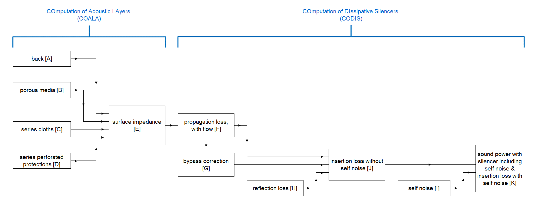
Fig. 8 Computation scheme (block-diagram) for the prediction of acoustic performance of silencers with the Module 1 of the software SILDIS® in case of locally reacting absorber
The routine COALA (COmputation of Acoustic LAyers) is a key computation step of the simulation software SILDIS®, of what outcome is the surface impedance of the multilayer acoustic structure considered, what is a physical quantity often used on the occasion of simulations relating to sound propagation. For the Module 1 of the software SILDIS®, this routine is accounting (as detailed in the next section) porous media, possibly supplemented by cloths or/and perforated protections.
In the context of the prediction of acoustic performance of silencers, this routine COALA is paired with the routine CODIS (COmputation of DIssipative Silencers), involving the derivation of the propagation loss with flow, of a by-pass correction, and of reflection loss - of what combination is resulting in insertion loss without self-noise - and also, in addition, the derivation of self-noise (i.e. noise generation due to flow) to finally get the sound power with silencer including self-noise and the insertion loss with self-noise, which are the ultimate results of the simulation.
Propagation loss is purely based on the solving of equations relating to plane waves sound propagation ; reflection loss, by-pass correction and flow noise are based on laboratory measurement results - i.e. on data pools at (testing) room temperature (as all input data considered for materials) -, with an extrapolation for thermodynamic conditions to be envisaged in any simulation context.
Therefore, outcome of the computation with the Module 1 of the software SILDIS® e.g. sound power level with silencer or insertion loss with self-noise are obtained by the means of a method which is not purely theoretical but in line with testings, where comparison with measurements is appropriate. Besides, a lot of comparisons have been succesfully carried out to check the consistence of results obtained on the one hand with the software SILDIS® and on the other hand by other recognized evaluation means: both for all computations steps as implemented considered separately and - of course - globally.
In case of an absorbing material layer being not locally reacting (then: possibly isotropic or anisotropic), computation scheme is adapted to take into account the sound transmission inside the absorber along flow direction.
In case of a silencer including side resonant cavities partially filled with a sound absorbing structure, the scheme of computation is also adjusted accordingly.
Main and special features, remarkable effects taken into account for the prediction of acoustic and aeraulic (aerodynamic) performance of silencers with Module 1 of software SILDIS®
Regarding acoustics, the main and special features of the software SILDIS® and remarkable effects taken into account in relation to the computation and sizing of silencers with the Module 1 can be listed as follows:
- the design is possible for multilayered acoustic structures: most sophisticated combination of materials which can be envisaged (for the lining/for half a splitter) is as shown on figure 9 (air flow according to x-axis, thickness of the lining/half a splitter according to y-axis)
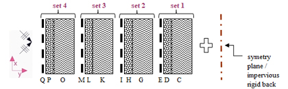
Fig. 9 Multilayered acoustic structure (i.e. combination of materials) considered for the prediction of acoustic performance of silencers with the Module 1 of the software SILDIS® - C, G, K, O : porous medium [3] - D, H, L, P : cloth [4] - E, I, M, Q : perforated protection [5]
Thus, acoustic structure basing the acoustic simulation can vary from layer C alone (e.g. in case of a single - naked - melamine foam filling) up to a combination of several soundproofing materials involving porous media, series cloths, series perforated protections depending on the needs (e.g. combination CDE can be used to simulate a mineral wool filling with a cloth and a perforated protection, unless CGK combination is used when all such layers are modelled as porous media [2]) (cf. fig. 9).For each layer, the input data characterizing its acoustical behavior (porous medium [3] i.e. C, G, K, O or cloth [4] i.e. D, H, L, P or perforated protection i.e. E, I, M, Q [5]) the user can:
- either select using materials referenced in dedicated libraries embedded in the software [6]
- or enter directly (BYO [7] concept)
- for an acoustic structure including a porous medium (e.g. polyester, rock wool, basalt wool, glass wool, foam … or which can be air or another fluid): behavior is taken into account on a microscopic scale level in relation to the properties such as flow resistivity (cf. fig. 10) and to other parameters for an absorber, either locally reacting or bulk reacting, then (in this last case), for the superficial layer, with a possible inhomogeneity of properties such as flow resistivity (σx, σy on figures below) or of other parameters, in directions respectively parallel (x) or perpendicular (y) to its surface (cf. fig. 11)
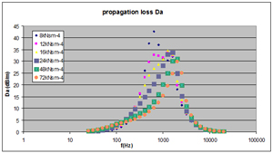
Fig. 10 Silencer propagation loss - influence of sound-absorbing filling flow resistivity (e.g. when variying from 8kNsm-4 to 72kNsm-4)
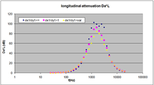
Fig. 11 Silencer longitudinal attenuation - influence of sound-absorbing filling anisotropy (e.g. locally reacting filling, isotropic filling, anisotropic filling)
- the effect of a laminated sound-absorbing filling (each porous layer being with different properties e.g. flow resistivity or other parameters) is taken into account (cf. fig. 12)
- the effect of a cloth (e.g. fabric, unwoven) is taken into account, both with regard to the resistance to airflow (cf. fig. 13) and with regard to the vibration of the membrane thus formed, what makes it possible to size, to some extent (e.g. when it comes to a limp plate or when rigidity can be accounted if mounting conditions are accurately known), silencers being not only pureley dissipative, but also resonant e.g. when one is looking for performance at low frequency specifically (notwithstanding calculations possible with the Module 1B of the SILDIS® software for the prediction of acoustic and aerodynamic performance of reactive silencers)
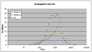
Fig. 12 Silencer propagation loss - comparison between sound-absorbing filling being monocomponent (e.g. with flow resistivity 12kNsm-4 or 72 kNsm-4) and bicomponent
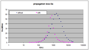
Fig. 13 Silencer propagation loss - influence of a cloth (with or without)
- the effect of a perforated protection (e.g. perforated sheet with circular holes and square or hexagonal array, or with square holes, and also: slotted superficial layer) is taken into account (cf. fig. 14): in terms of sound propagation inside perforations (drillings) and in terms of interaction with a porous medium at the front/at the rear are taken into account
- by-pass correction is taken into account (cf. fig. 15)
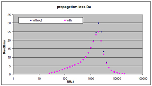
Fig. 14 Silencer propagation loss - influence of a perforated protection (with or without)
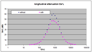
Fig. 15 Silencer attenuation: influence of by-pass correction (with or without)
- reflection loss is taken into account (cf. fig. 16)
- effect of temperature is taken into account (cf. fig.17)
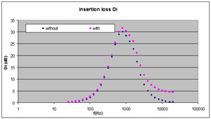
Fig. 16 Noise reduction by the means of a silencer - influence of reflection loss (with or without)
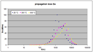
Fig. 17 Silencer propagation loss - influence of temperature (e.g. 20°C, 300°C, 600°C)
- effect of pressure is taken into account (cf. fig.18)
- effects of fluid flow velocity are taken into account: on the one hand otherwise than via self-noise (cf. fig. 19) - the distinction is then made between the cases where sound and fluid propagate either in opposite directions (intake: minus sign for speed) or in the same direction (exhaust: plus sign for speed) -, and on the other hand via self-noise (cf. fig. 20)
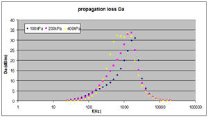
Fig. 18 Silencer propagation loss - influence of pressure (e.g. 100kPa, 200 kPa, 400 kPa)
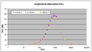
Fig. 19 Silencer longitudinal attenuation - influence of gas (fluid) speed (e.g. 0 m/s, -10 m/s, 20 m/s)
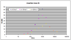
Fig. 20 Silencer insertion loss - influence of self noise (i.e. flow noise) in relation to gas (fluid) speed (e.g. 0 m/s, -10 m/s, 20 m/s)
Regarding aeraulics (aerodynamics), different geometries for the splitters/the sound-absorbing lining are possible for both upstream and downstream e.g. extremity with rectangular, semi-circular shape (or even more aerodynamically profiled: downstream only).
Main displayed results (tables and graphs) in terms of acoustic and aeraulic (aerodynamic) performance of silencers with Module 1 of software SILDIS®
Main displayed results (tables and graphs) in terms of acoustic and aeraulic (aerodynamic) performance of silencers with Module 1 of software SILDIS® are as follows:
- insertion loss without flow: per 1/3 octave frequency band and 1/1 octave frequency band (as well as A-weighted overall value with respect to a reference spectrum, as detailed below), for 3 usual conditions of propagation of sound inside the lining (as detailed below)
- insertion loss with flow without self-noise Di’ (cf. fig. 21 and 22), detailing longitudinal attenuation Da.L (cf. fig. 23) for single frequencies as far as the curve is concerned, bypass correction Dk (cf. fig. 24) and reflection loss Dr (cf. fig. 25) for single frequencies as far as the curve is concerned, all of this per 1/3 frequency band and 1/1 octave frequency band (as well as A-weighted overall value with respect to a reference spectrum entered by user, either in 1/3 octave frequency band and 1/1 octave frequency band), for 3 usual conditions of propagation of sound inside the absorbing lining/baffles, based on following assumptions: ratio of resistivities according to y-axis and x-axis i.e. σy/σx possibly infinite (locally reacting absorber), equal to 1 (isotropic absorber) or with a customizable value (anisotropic absorber)
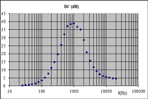
Fig. 21 Silencer insertion loss without self-noise i.e. without flow noise (curve)
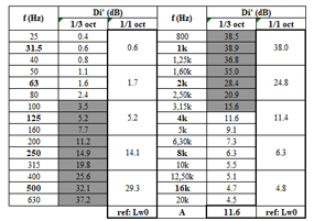
Fig. 22 Silencer insertion loss without self-noise i.e. without flow noise (table)
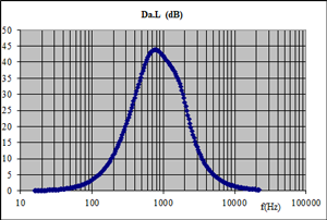
Fig. 23 Silencer propagation loss depending on frequency
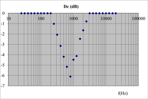
Fig. 24 Silencer by-pass correction
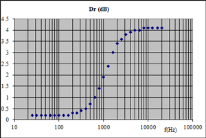
Fig. 25 Silencer reflection loss
- self-noise (sound power level of flow noise) per 1/1 octave frequency band (as well as A-weighted overall value)
- A-weighted and not A-weighted sound power level with silencer Lw1, per 1/1 octave frequency band and overall, for 3 usual conditions of propagation of sound inside the absorbing lining (as detailled above), comparable (for the sake of evaluation of the efficiency of the studied soundproofing device) with the sound power level without silencer Lw0) (cf. fig. 26)
- insertion loss with flow and self-noise, per 1/3 and 1/1 octave frequency band (as well as A-weighted overall value with respect to a reference spectrum as detailed above), for 3 usual conditions of propagation of sound inside the lining (as detailed above) (cf. fig. 27)
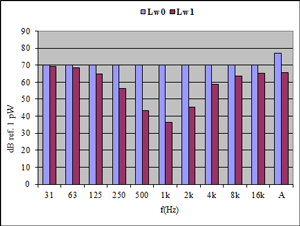
Fig. 26 Sound power level with or without silencer
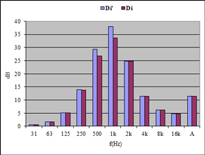
Fig. 27 Silencer insertion loss with or without consideration of flow noise (aka self noise), respectively Di and Di'
- total pressure loss (and non-dimensional total pressure loss coefficient)
The results of the calculations are comparable with the standardized measurement: see NF EN ISO 7235 Acoustics - Laboratory measurement procedures for ducted silencers and air terminal units - Insertion loss, flow noise and total pressure loss.
When it is not a question of rectangular silencers with splitters (baffles) of which transverse dimensions is (as per figure 1) equal to the height H of the casing, and if it does not come to a configuration foreseen in the context of the Module 1, simulations are also possible with the SILDIS® software for the prediction of acoustic and aeraulic (aerodynamic) performance of silencers with discontinued splitters: cf. Module 1A.
Complementary displayed results (tables and graphs) in terms of acoustics with Module 1+ of software SILDIS®
With the so-called Module 1+ of the software SILDIS® (which is an extended version of Module 1), complementary displayed results (tables and graphs) in terms of acoustics, for the multilayer structure used to model the lining/half a splitter (with an impervious rigid back/a symmetry plane), are as follows:
- surface impedance: Z, complex quantity i.e. with a real part and with an imaginary part (cf. fig. 28 and fig. 29), per 1/3 and 1/1 octave frequency band , for single frequencies as far as the curve is concerned ; and also: normalized impedance Z/Z0 (compared to the characteristic impedance Z0 of the considered fluid, in the considered thermodynamic context)
- the surface admittance G = 1/Z, complex quantity i.e. with a real part and an imaginary part, in the form of a table which can, after a simple copying and a simple pasting, constitute an input file for calculations with other tools (e.g. based on finite element or boundary element methods) when the latter do not have, for the determination of these quantities, functionalities as powerful as those of the SILDIS® software
- absorption coefficient at normal incidence: α0 i.e. alpha 0 (cf. fig. 30) per 1/3 and 1/1 octave frequency band, for single frequencies as far as the curve is concerned
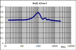
Fig. 28 Surface impedance of a multilayered acoustic structure: real part
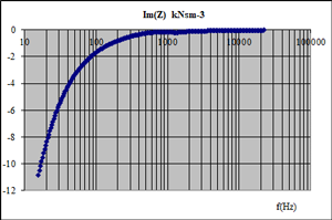
Fig. 29 Surface impedance of a multilayered acoustic structure: imaginary part
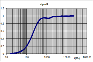
Fig. 30 Sound absorption coefficient for normal incidence of a multilayer structure (with an impervious rigid back)
The results of the calculations are comparable with the standardized measurement: see ISO 10534-1 Acoustics - Determination of sound absorption coefficient and impedance in impedance tubes - Part 1: Method using standing wave ratio.
It is no insignificant matter: evaluations of Z and G as mentioned above can be carried out also with the consideration of a curvature radius, as necessary in case of silencers with a round cross section.
Supplement relating to Module 1A of software SILDIS® for the prediction of acoustic and aeraulic (aerodynamic) performance of silencers with discontinued splitters
Whereas the general context of use of the silencers that Module 1A allows to size is the same as that prevailing for the use of Module 1, what was mentioned above with regard to the possible applications for the prediction of acoustic performance and aeraulics (aerodynamics) of the silencers with Module 1 of the SILDIS® software must, as regards Module 1A, be amended.
Indeed, unlike Module 1, Module 1A allows calculations:
- for rectangular silencers with splitters (baffles) whose transverse dimension is not (as in figure 1) equal to the height H of the duct, but is lower, as shown in figure 31
- for circular silencers with non-hollowed pod as illustrated in figure 32 (for which only the geometric parameters distinguish it from figure 4), with a performance determination which is not (whereas this is the case with Module 1) directly based on an analytical approach involving Bessel and Neumann functions, the evaluation of which may show imperfections in the case of silencers of very large cross section; it is minor to know that Module 1A allowed calculations for this silencer geometry long before they were made possible with Module 1, at the cost of very significant developments.
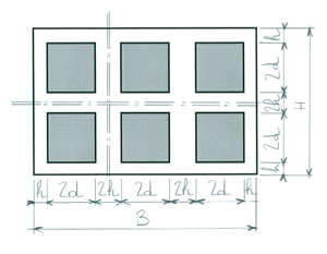
Fig. 31 Rectangular silencer with discontinued splitters
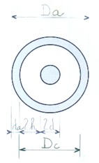
Fig. 32 Cylindrical silencer with non-hollowed pod for wich calculations are possible with the Module 1A of software SILDIS®
What was mentioned above about the computation scheme (bloc diagram) for the prediction of the acoustic performance of dissipative silencers with Module 1 and also about the main and special features, and the remarkable effects taken into account must, for what concerns Module 1A, be amended.
Indeed, unlike Module 1, the evaluation of propagation loss is based on interpolations and extrapolations of propagation loss values per unit airway width (involving a dimensionless parameter combining axial attenuation & dimension of the airways) for a series of values of another dimensionless parameter combining dimension of the airways and wavelength, resulting from a multifactorial parametric study of databases of simulation results (carried out with means other than SILDIS®), for combinations of open area ratio and material thicknesses (depending on the case: isotropic or anisotropic, however with limited resistivity variability, cloth and perforated protection assumed to have negligible influence), and this for different values of the Mach number (depending on the case: positive, negative or zero).
What was mentioned above about the main results displayed (tables and graphs) in terms of acoustic and aeraulic (aerodynamic) performance of silencers with Module 1 of the SILDIS® software is also valid for Module 1A.
What can be added, in relation to the prediction of the acoustic and aeraulic (aerodynamic) performances of silencers with Modules 1 / 1+ / 1A of the SILDIS® software
This easy-to-use, reliable and precise calculation tool is particularly appropriate for the development of noise attenuators in many contexts:
- for ordinary applications (e.g. in the building sector: ventilation and air conditioning networks): when it is desired to prepare laboratory measurements (e.g. for the purpose of having official test reports) by optimizing the configurations tested and limiting their number ; when one wishes to have acoustic performance evaluations for which the accuracy is beyond that corresponding to values provided for a wide range of air speeds, without distinction of the respective directions of the sound propagation and of the air flow
- for special applications (e.g. in the industrial sector, but not only): when one wishes to overcome the limitations linked to the inherently restricted nature of the data resulting from laboratory measurements - which do generally only relate to ordinary temperatures and pressures, standard packing materials, moderate fluid speeds, fixed combinations of geometrical parameters (e.g. thickness of the absorbing lining/splitters, airways, length), for which the interpolations are subjected to uncertainties that are sometimes significant and for which extrapolations are risky
The prediction of acoustic and aeraulic (aerodynamic) performance of silencers with the Modules 1 / 1+ / 1A of the software SILDIS® can be carried out either by the human resources of ITS (which developed and which markets this simulation tool: software publishing is an ITS activity assessed to meet the requirements of standard ISO 9001), or by self-service (with subscription) in ASP [8] mode.
[1] https://www.its-acoustique.fr/images/stories/pdf/report_phrxx-008x.pdf
[2] some cloths and some perforated protections can also be considered as porous layers for the computation
[3] characteristics taken into account: resistivity, porosity, tortuosity, thermal characteristic length, viscous characteristic length, density, thickness
[4] characteristics taken into account: resistance to air flow, mass density, thickness
[5] characteristics taken into account: porosity, geometry of the perforations, mass density, thickness
[6] selected among a software library including for each kind of layer more than 20 referenced materials
[7] BYO = Bring Your Own (anglo-australian acronym)
[8] ASP = Application Service Provider from 250 €/month i.e. 277.50 US $/month ; the fixed price is that indicated in € (the price expressed in US $ is valid, as on December 5, 2019, when 1 € = 1.11 US $) ; VAT with a rate of 20% extra (if applicable, i.e. only for customers established in France) ; commissioning extra